Printer, printer control method of printer and non-transitory computer-readable medium

Pending Publication Date: 2022-05-26
SATO HLDG CORP
View PDF0 Cites 0 Cited by
  • Summary
  • Abstract
  • Description
  • Claims
  • Application Information

AI Technical Summary

Benefits of technology

The technical effect of this patent is to improve the efficiency of identifying the best placement for an antenna. The invention provides a printer that can quickly and accurately find the most effective position for an antenna.

Problems solved by technology

In the conventional art, the antenna position is identified on the basis of an initial position and a final position at which communication with the RFID was successful, and thus there were cases where an optimum antenna position could not be efficiently identified.

Method used


Image

  • Printer, printer control method of printer and non-transitory computer-readable medium
  • Printer, printer control method of printer and non-transitory computer-readable medium
  • Printer, printer control method of printer and non-transitory computer-readable medium

Examples


Embodiment Construction

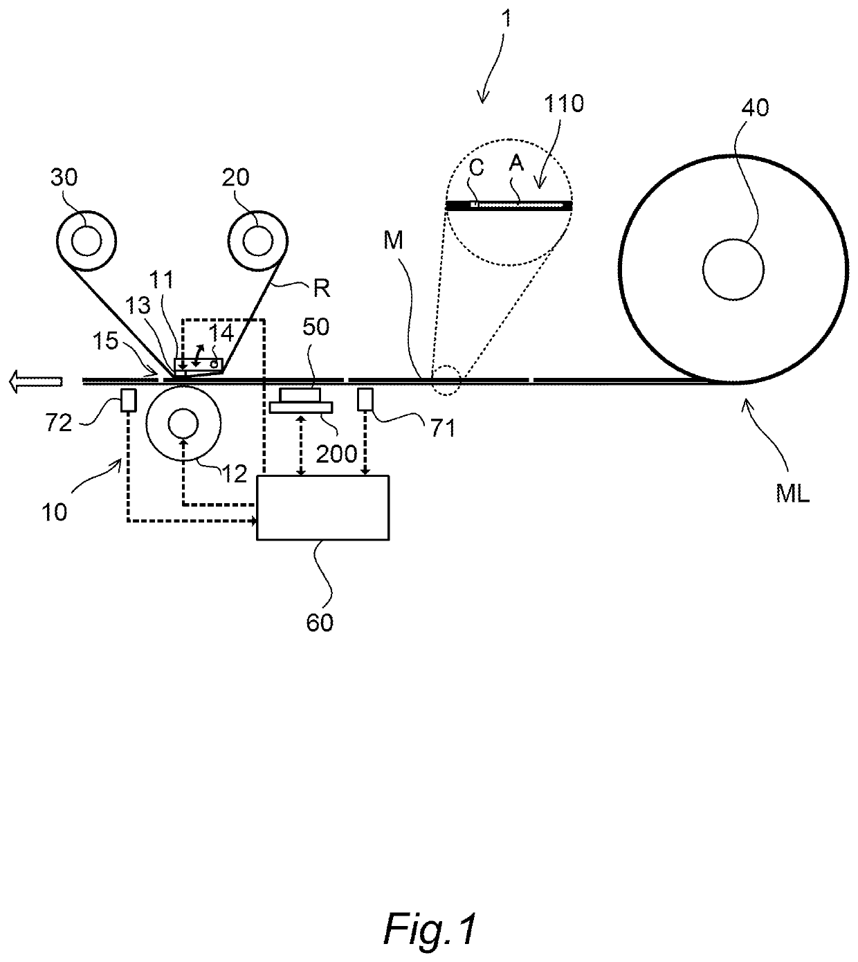
[0025]The following describes a printer 1 according to embodiments of the present invention in detail with reference to the attached drawings. FIG. 1 is a schematic configuration diagram of a printer 1 according to an embodiment of the present invention.

[0026]The printer 1 is of a thermal transfer type that prints by heating an ink ribbon R and transferring the ink of the ink ribbon R onto a print medium M. The print medium M is configured, for example, as a continuous body ML on which a plurality of labels are continuously attached temporarily at predefined intervals on a band-form backing paper and which is wound as a roll shape.

[0027]The print medium M is configured as an RFID (Radio Frequency Identification) medium embedded with an RFID inlet 110 having an IC chip C of the RFID specification and an antenna A. The printer 1 may also print on a printing medium having no IC chip C or antenna A.

[0028]The printer 1 prints variable information such as prices, barcodes, other product i...


PUM


Abstract

A printer configured to print on a printing medium having an RFID, comprising a communication unit configured to communicate with the RFID, and a search unit configured to move the communication unit to a position with respect to the RFID to search for a position communicable with the RFID, wherein the search unit determines communication success / failure between the RFID and the communication unit at a plurality of positions with respect to the RFID, and on the basis of a region including a plurality of positions determined as the communication being successful, identifying a communication position between the RFID and the communication unit.

Description

TECHNICAL FIELD[0001]The present invention relates to a printer, a printer control method of printer and program.BACKGROUND ART[0002]RFID (Radio Frequency Identification) technology transmits and receives, via contactless communication, information on an IC chip on which identification information is written, and is applied in various fields. JP2003-29669A discloses a printer that writes in information to an RFID element without contact, as well as printing on label paper embedded with an RFID element.SUMMARY OF INVENTION[0003]In the conventional art, the antenna position is identified on the basis of an initial position and a final position at which communication with the RFID was successful, and thus there were cases where an optimum antenna position could not be efficiently identified.[0004]In view of such technical problem, an object of the present invention is to more efficiently identify an optimum antenna position.[0005]According to one aspect of the present invention, a prin...

Claims


Application Information

Patent Timeline
IPC IPC(8): B41J3/407B41J3/50G06K7/015
CPCB41J3/4075G06K7/015B41J3/50G06K17/0029
Inventor ARAI, HIDEKAZUSAITO, YUJI
Owner SATO HLDG CORP
Why Eureka
Try Eureka