Energy management in a network

Active Publication Date: 2020-11-10
BRITISH TELECOMM PLC
View PDF70 Cites 38 Cited by
  • Summary
  • Abstract
  • Description
  • Claims
  • Application Information

AI Technical Summary

Benefits of technology

The present invention provides a network management method for managing energy usage in a network by analyzing network elements, identifying routes, and switching between alternative routes to optimize energy usage. The method can be used to manage proactively the energy usage of a network without relying upon setting arbitrary caps on the total energy used for a route or allowing clients to select energy-efficient routes that may not be in their best interests. Instead, the method can enable intelligent reshaping of the network to provide more energy efficient usage of the network as a whole and of routing through the network. The method can also be used to manage QoS factors while reducing energy consumption. The analysis of network elements can be done based on traffic utilization, and the method can identify and target those elements with low traffic utilization for energy savings. Overall, the invention provides a method for managing energy usage in a network that is efficient and effective.

Problems solved by technology

Network devices used to implement large-scale computer networks are high consumers of energy and often consume significant energy even when they are not carrying significant volumes of network traffic.
Typically, it is the network operator who might be concerned about energy usage in the network but actions to manage energy usage can drive network traffic to other operators if aggressive energy management causes a shortfall in capacity on the network.
This may reduce the analysis needed to identify the next candidate network elements.
As the quality of service that is capable of being delivered decreases, the loss increases to eventually trigger reactivation of one or more network devices.

Method used


Image

  • Energy management in a network
  • Energy management in a network
  • Energy management in a network

Examples


Embodiment Construction

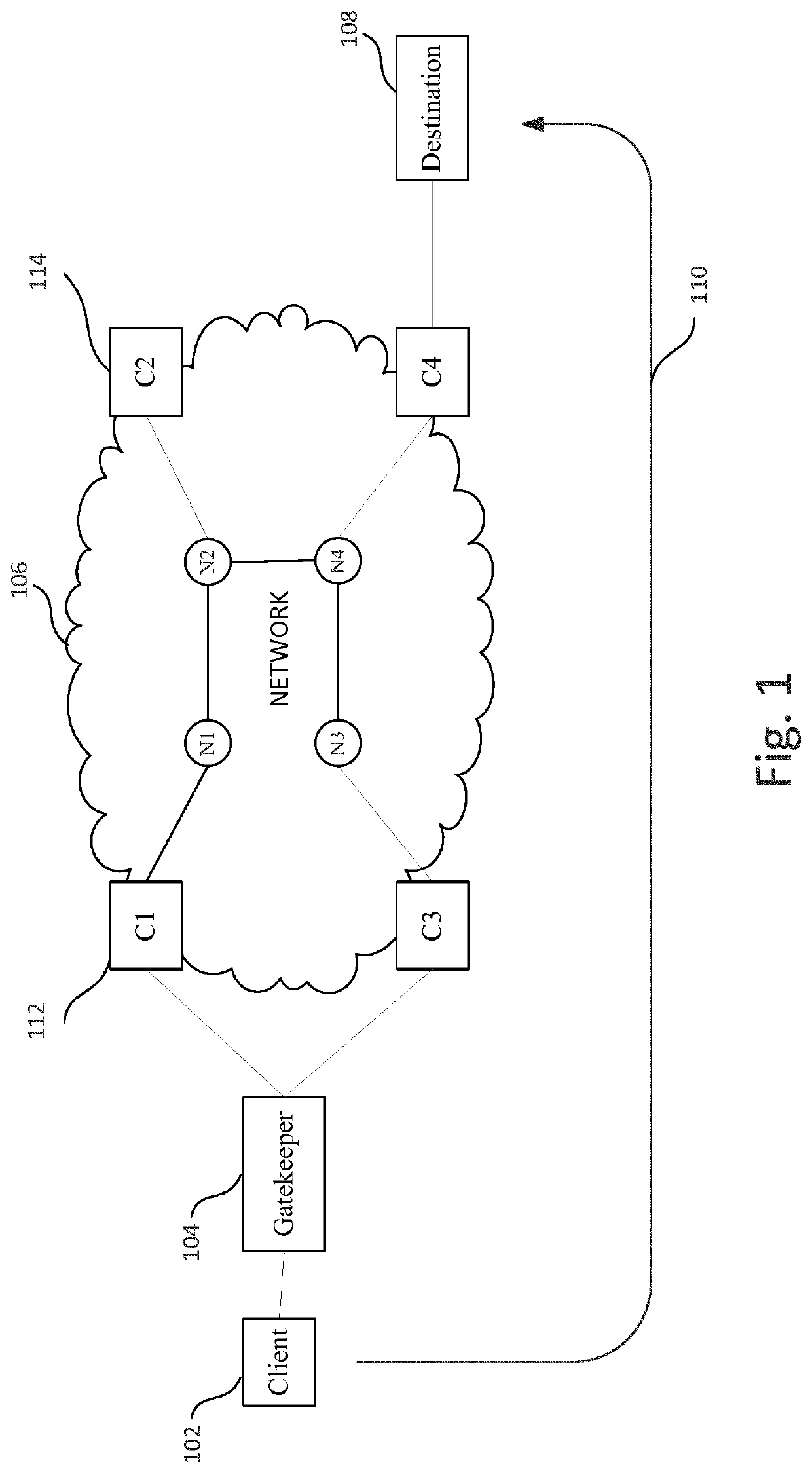
[0076]By way of background, as described in more detail below, the present system may be implemented in an environment of dynamic QoS models and some of those models can be related to energy utilisation. This can enable a client to request, in their set of desired QoS models with an associated priority, the best possible energy behaviour, i.e. a route with the lowest energy utilisation that still satisfies their performance criteria. Alternatively, or in addition, an operator can enforce a priority list, one of those being energy utilisation, and prefer routes that provide optimal energy utilisation over ones that do not. This operator-enforced priority is important if the operator finds that the clients do not choose such priorities as they are likely to benefit the operator more than the client. Furthermore, an operator can choose to incorporate energy utilisation into the dynamic pricing model. It is also possible for a network operator to enforce a maximum bound in energy utilis...


PUM


Abstract

A network management method is described for managing energy utilisation in a network comprising network elements that handle network traffic. The network elements are analysed to identify at least one candidate network element for energy usage reduction. Routes passing through the candidate network element are then identified and at least one alternative route is identified for each identified route. Each identified route is switched onto the at least one alternative route, wherein the alternative route does not pass through the original candidate network element. Finally, the candidate network element is triggered to enter a lower power mode. In a particular embodiment, a quality of service level associated with each identified route is determined and the method ensures that the alternative route has an associated quality of service level equal to or better than the original quality of service level. Systems and apparatus for implementing the method are also described.

Description

[0001]This application is the U.S. national phase of International Application No. PCT / EP2016 / 065422 filed Jun. 30, 2016 which designated the U.S. and claims priority to EP Patent Application No. 15275166.5 filed Jun. 30, 2015, EP Patent Application No. 15187163.9 filed Sep. 28, 2015, EP Patent Application No. 15187813.9 filed Sep. 30, 2015 and EP Patent Application No. 16162450.7 filed Mar. 24, 2016, the entire contents of each of which are hereby incorporated by reference.BACKGROUND AND SUMMARY[0002]The present invention relates to the field of network management, in particular the management of a network in relation to its energy usage and the energy usage of devices within the network.[0003]Network devices used to implement large-scale computer networks are high consumers of energy and often consume significant energy even when they are not carrying significant volumes of network traffic. However, when a client device selects a QoS, and therefore a route for a particular traffic...

Claims


Application Information

Patent Timeline
IPC IPC(8): H04L12/24H04L12/721H04L12/26H04L12/707G06F1/3203G06F1/3287H04L12/725H04L45/24
CPCH04L43/0876H04L45/22H04L41/0833H04L41/5025H04L45/124H04L41/145H04L45/302G06F1/3203G06F1/3287H04L43/08
Inventor KARTHIKEYAN, VIDHYALAKSHMINAUCK, DETLEF
Owner BRITISH TELECOMM PLC
Why Eureka
Try Eureka