

Lightweight Table Providing a Protective Shield
a technology of shielding and light weight, applied in the field of tables, can solve the problems of low projectile resistance and unsuitability for table support, and achieve the effect of low projectile resistance and high stiffness
- Summary
- Abstract
- Description
- Claims
- Application Information
AI Technical Summary
Benefits of technology
Problems solved by technology
Method used
Image

Examples
Embodiment Construction
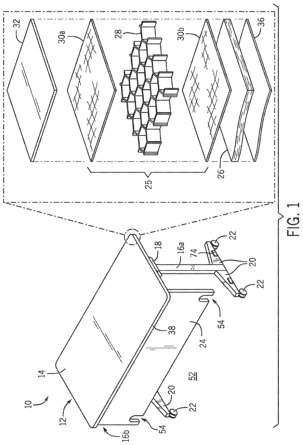
[0043]Referring now to FIG. 1, a table 10 constructed according to one embodiment of the present invention provides a generally planar and rectangular tabletop 12 having an upper surface 14. In one non-limiting example, the upper surface 14 may present a smooth laminate material which in one embodiment may provide a dry-erase marker surface, the latter being a smooth, white non-absorptive surface for receiving dry marker inks and allowing their removal. In one non-limiting example, the tabletop 12 may be 5 feet long and 24 inches wide and more generally at least 4 feet long and at least 18 inches wide.
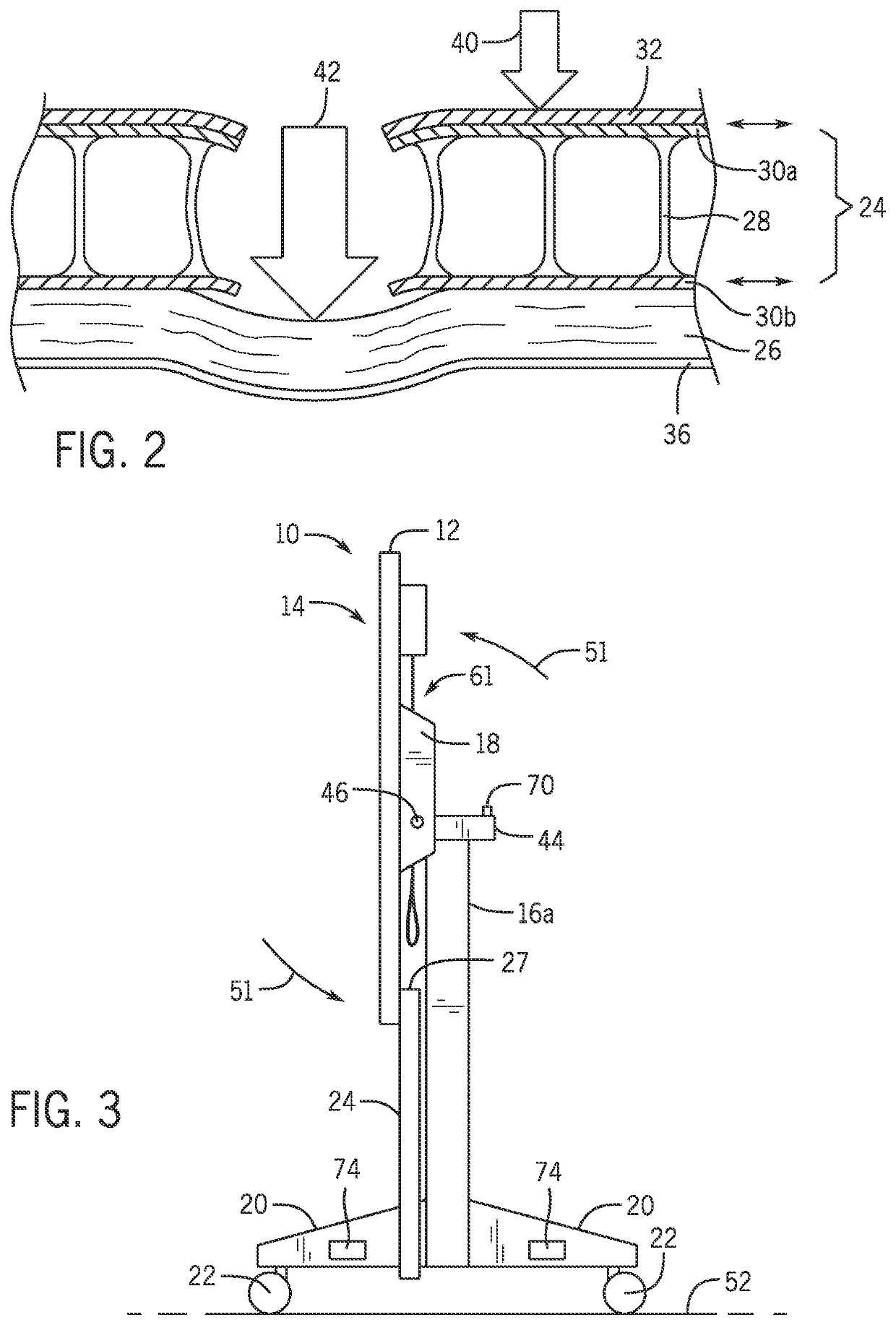
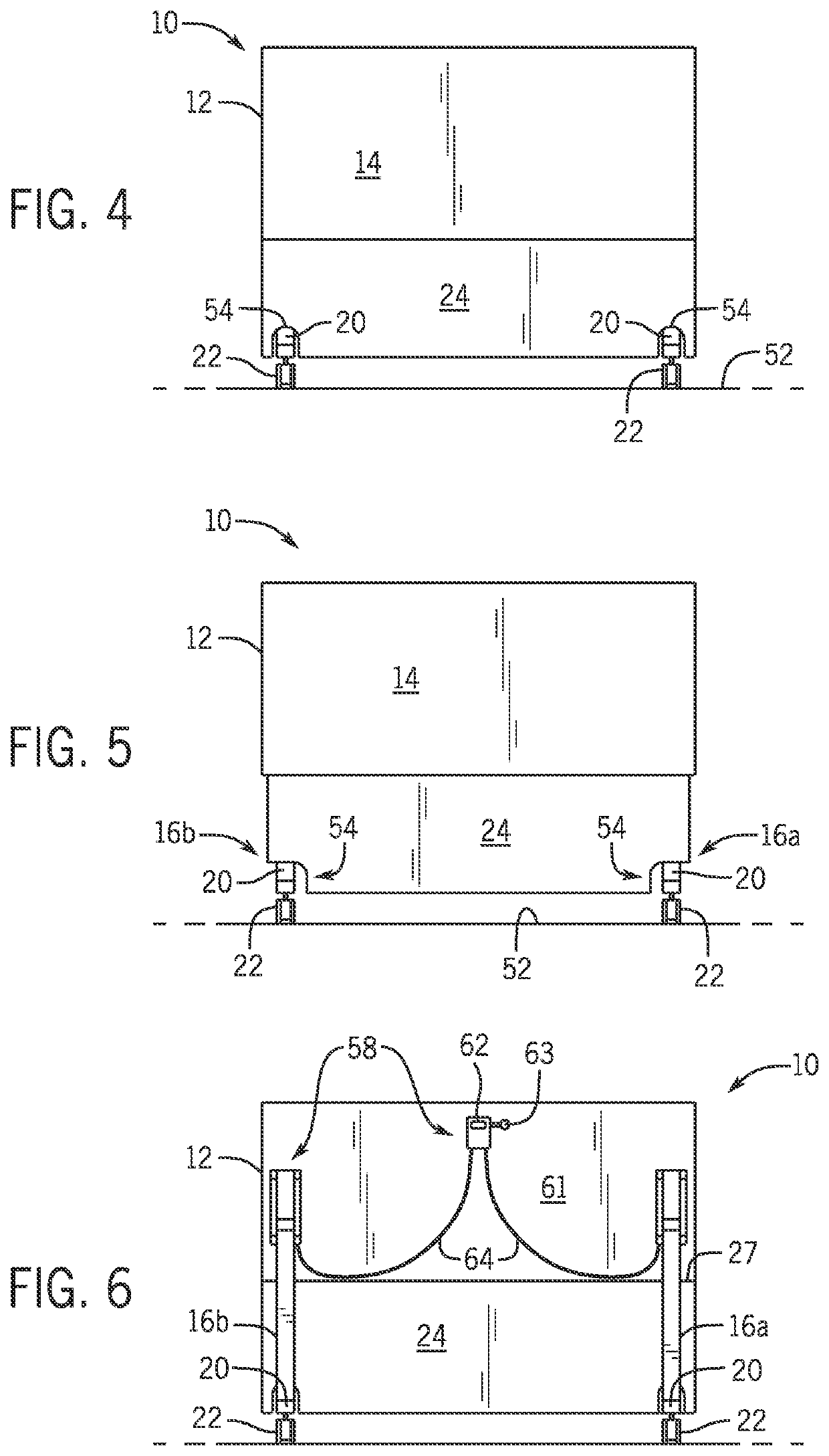
[0044]The underside of the tabletop 12 may be supported by downwardly extending pillars 16a and 16b located at opposite longitudinal ends of the tabletop 12 along a centerline extending along the longest dimension of the tabletop 12. The pillars 16 may attach to the tabletop, at their upper ends, by means of brackets 18 attached to the underside of the tabletop 12 as will be described...
PUM
 Abstract
Description
Claims
Application Information