Automatic battery replacement apparatus, moving platform, and rechargeable battery

a technology of automatic battery replacement and moving platform, which is applied in the direction of batteries/cells, secondary cells servicing/maintenance, battery/cell propulsion, etc., and can solve the problem of reducing the operation efficiency of the conventional moving platform

Pending Publication Date: 2022-06-09
ALICORP
View PDF0 Cites 0 Cited by
  • Summary
  • Abstract
  • Description
  • Claims
  • Application Information

AI Technical Summary

Benefits of technology

[0005]In response to the above-referenced technical inadequacy, the present disclosure provides an automatic battery replacement ap...

Problems solved by technology

However, a charging mechanism of the conventional moving platform would stop the operation of the con...

Method used


Image

  • Automatic battery replacement apparatus, moving platform, and rechargeable battery
  • Automatic battery replacement apparatus, moving platform, and rechargeable battery
  • Automatic battery replacement apparatus, moving platform, and rechargeable battery

Examples


first embodiment

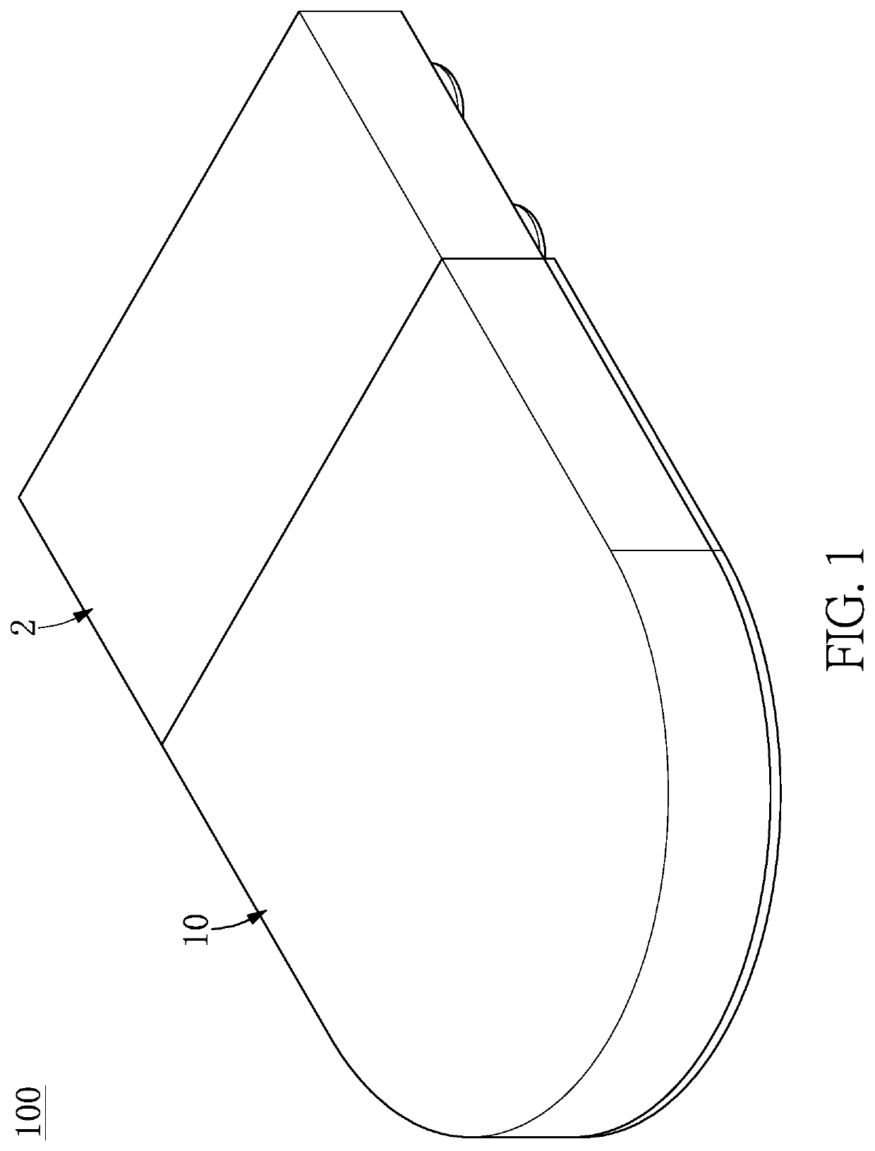
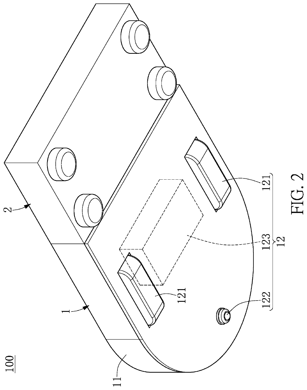
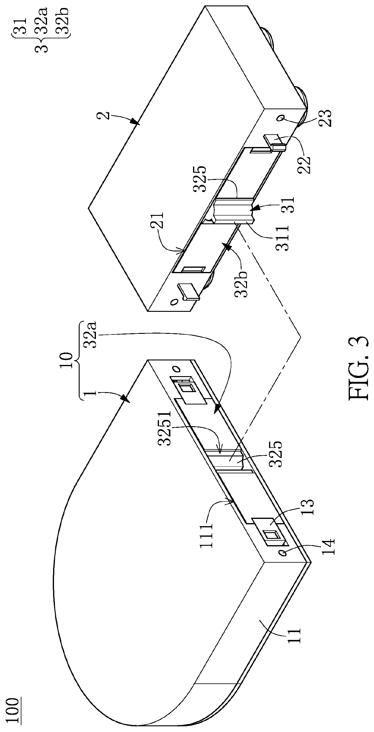
[0029]Referring to FIG. 1 to FIG. 11, a first embodiment of the present disclosure provides an automatic battery replacement apparatus 100. As shown in FIG. 1 to FIG. 3, the automatic battery replacement apparatus 100 includes a movable carrier 1, a charging station 2, and a battery replacement module 3 that is assembled to the movable carrier 1 and the charging station 2. The battery replacement module 3 includes a driving gear 31 and two rechargeable batteries 32a, 32b. The two rechargeable batteries 32a, 32b are respectively assembled to the movable carrier 1 and the charging station 2, and positions of the two rechargeable batteries 32a, 32b can be interchanged with each other through the driving gear 31.

[0030]It should be noted that the movable carrier 1 in the present embodiment is described in cooperation with the charging station 2 and the battery replacement module 3, but the present disclosure is not limited thereto. For example, the movable carrier 1 and the rechargeable ...

second embodiment

[0062]Referring to FIG. 12 and FIG. 13, a second embodiment of the present disclosure is similar to the first embodiment of the present disclosure. For the sake of brevity, descriptions of the same components in the first and second embodiments of the present disclosure will be omitted herein, and the following description only discloses different features between the first and second embodiments.

[0063]In the present embodiment, the automatic battery replacement apparatus 100 further includes a plurality of side auxiliary wheels 5 and a plurality of forward auxiliary wheels 6. The side auxiliary wheels 5 are respectively arranged in the moving platform 10 between the inner lateral wall of the power supply slot 111 and the rechargeable battery 32a and in the charging station 2 between the inner lateral wall of the charging slot 21 and the rechargeable battery 32b. Moreover, the forward auxiliary wheels 6 are respectively arranged in the moving platform 10 between a bottom wall of the...

third embodiment

[0066]Referring to FIG. 14, a third embodiment of the present disclosure is similar to the first and second embodiments of the present disclosure. For the sake of brevity, descriptions of the same components in the first to third embodiments of the present disclosure will be omitted herein, and the following description only discloses different features between the third embodiment and the first and second embodiments.

[0067]In the present embodiment, the connecting side 323 of each of the two rechargeable batteries 32a, 32b can be in a shape of an arc, and the connecting side 323 of the rechargeable battery 32a is flush with the outer surface of the carrying body 11 adjacent thereto, so that the moving platform 10 can be substantially in a circular shape. Moreover, the movable carrier 1 and the charging station 2 can be adjusted according to the connecting side 323 of each of the two rechargeable batteries 32a, 32b and the design requirements.


PUM


Abstract

An automatic battery replacement apparatus, a moving platform, and a rechargeable battery are provided. The moving platform includes a movable carrier and the rechargeable battery assembled in the movable carrier. The movable carrier includes a carrying body and a moving component that is assembled to the carrying body. The carrying body has a power supply slot recessed in an outer surface thereof, and an inner lateral wall of the power supply slot is in a shape of an arc having a central angle that is less than or equal to 180 degrees. The moving component is configured to move on a working surface. The rechargeable battery has a matching structure configured to be engaged with a driving gear. The rechargeable battery is configured to be rotated along the inner lateral wall of the power supply slot by having the matching structure engaged with the driving gear.

Description

CROSS-REFERENCE TO RELATED PATENT APPLICATION[0001]This application claims the benefit of priority to China Patent Application No. 202011413950.9, filed on Dec. 4, 2020 in People's Republic of China. The entire content of the above identified application is incorporated herein by reference.[0002]Some references, which may include patents, patent applications and various publications, may be cited and discussed in the description of this disclosure. The citation and / or discussion of such references is provided merely to clarify the description of the present disclosure and is not an admission that any such reference is “prior art” to the disclosure described herein. All references cited and discussed in this specification are incorporated herein by reference in their entireties and to the same extent as if each reference was individually incorporated by reference.FIELD OF THE DISCLOSURE[0003]The present disclosure relates to a battery replacement mechanism, and more particularly to a...

Claims


Application Information

Patent Timeline
IPC IPC(8): B60L53/80H02J7/00B65G67/02H01M10/44
CPCB60L53/80H02J7/0045H01M2220/30B65G67/02H01M10/44H02J7/0013H02J7/36H02J2310/48B60L50/66B60L50/64B60L2200/40B60L2260/32H01M2220/20H01M50/262H01M10/46H01M50/207A47L9/2873A47L9/2884A47L2201/02
Inventor YANG, MING-YUAN
Owner ALICORP
Why Eureka
Try Eureka