Robot, control processing method, and non-transitory computer readable recording medium storing control processing program

a control processing and computer readable recording medium technology, applied in the field of robots, control processing methods, and non-transitory computer readable recording mediums storing control processing programs, can solve the problems of difficult to bring out a good facial expression from a subject, and further improvement is required, and achieves a pleasant atmosphere and good facial expression.

Pending Publication Date: 2022-06-09
PANASONIC INTELLECTUAL PROPERTY CORP OF AMERICA
View PDF0 Cites 0 Cited by
  • Summary
  • Abstract
  • Description
  • Claims
  • Application Information

AI Technical Summary

Benefits of technology

[0008]According to the present disclosure, a space with a pleasant atmosphere can be provided to one or more subjects, and a good facial expression can be brought out from the one or more subjects.

Problems solved by technology

However, in the above-described conventional technique, it is difficult to bring out a good facial expression from a subject, and further improvement is required.

Method used


Image

  • Robot, control processing method, and non-transitory computer readable recording medium storing control processing program
  • Robot, control processing method, and non-transitory computer readable recording medium storing control processing program
  • Robot, control processing method, and non-transitory computer readable recording medium storing control processing program

Examples


first embodiment

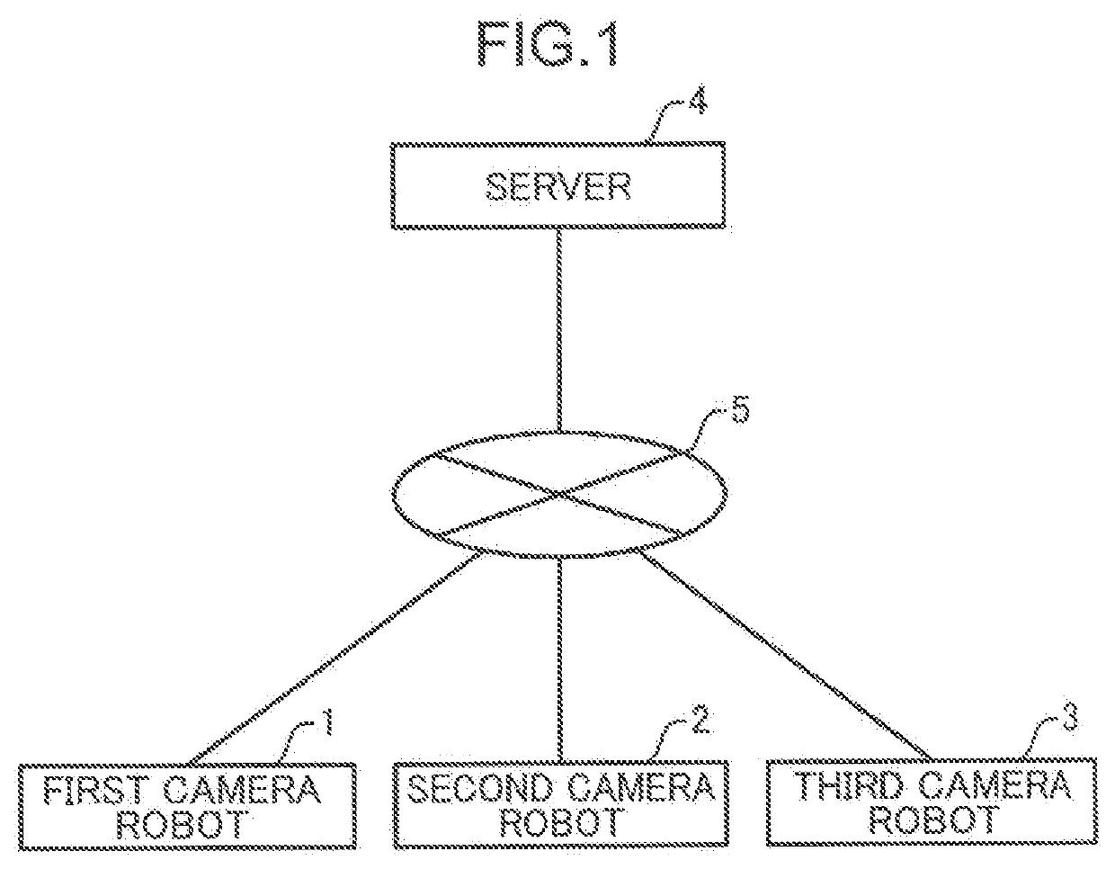
[0056]FIG. 1 is a diagram illustrating an overall configuration of an imaging system according to a first embodiment of the present disclosure.

[0057]The imaging system illustrated in FIG. 1 includes a first camera robot 1, a second camera robot 2, a third camera robot 3, and a server 4.

[0058]The first camera robot 1, the second camera robot 2, and the third camera robot 3 are arranged in the same space at home. The first camera robot 1, the second camera robot 2, and the third camera robot 3 are arranged in a living room, for example. Each of the first camera robot 1, the second camera robot 2, and the third camera robot 3 detects one or more subjects and captures an image of the detected one or more subjects. The subject is a person.

[0059]The first camera robot 1, the second camera robot 2, and the third camera robot 3 are communicably connected to each other via a network 5. One of the first camera robot 1, the second camera robot 2, and the third camera robot 3 selects an operati...

second embodiment

[0137]Next, an imaging system according to a second embodiment of the present disclosure will be described.

[0138]In the second embodiment, in addition to the first operation pattern and the second operation pattern of the first embodiment, a third operation pattern and a fourth operation pattern are selected which represent a situation in which one of a plurality of camera robots is lifted.

[0139]FIG. 10 is a block diagram illustrating a configuration of a first camera robot according to the second embodiment of the present disclosure. The imaging system according to the second embodiment includes a first camera robot 1A, a second camera robot 2A, a third camera robot 3A, and a server 4. Since the configurations of the second camera robot 2A and the third camera robot 3A are the same as the configuration of the first camera robot 1A, only the configuration of the first camera robot 1A will be described. In the second embodiment, the same components as those in the first embodiment ar...

third embodiment

[0188]Next, an imaging system according to a third embodiment of the present disclosure will be described.

[0189]In the third embodiment, in addition to the first operation pattern and the second operation pattern of the first embodiment, a fifth operation pattern is selected which represents a situation in which a plurality of camera robots output sound from a speaker in accordance with a rhythm of music.

[0190]FIG. 17 is a block diagram illustrating a configuration of a first camera robot according to the third embodiment of the present disclosure. The imaging system according to the third embodiment includes a first camera robot 1B, a second camera robot 2B, a third camera robot 3B, and a server 4. Since configurations of the second camera robot 2B and the third camera robot 3B are the same as the configuration of the first camera robot 1B, only the configuration of the first camera robot 1B will be described. In the third embodiment, the same components as those in the first embod...


PUM


Abstract

A first camera robot includes: a camera that captures an image of surroundings; an image recognizer that detects one or more subjects from within a captured image; a controller that selects an operation pattern of the first camera robot based on an attribute of one or more subjects detected, and causes the robot to operate according to the selected operation pattern; a communicator that transmits, to another camera robot, instruction information for causing the other robot to operate according to the selected operation pattern; and a shutter that outputs an image obtained by capturing the one or more subjects while the first camera robot and the other robot are operating according to the selected operation pattern.

Description

TECHNICAL FIELD[0001]The present disclosure relates to a technique for capturing an image of one or more subjects through operation together with another robot.BACKGROUND ART[0002]In recent years, various robots have been introduced into the market. In addition, a technique has also been developed in which a plurality of robots each having a camera perform cooperative operation.[0003]For example, Patent Literature 1 discloses a robot camera device in which a plurality of robot cameras exchange photographing information with each other and perform cooperative operation to automatically perform photographing according to a situation, and a person operates the robot camera as necessary.[0004]However, in the above-described conventional technique, it is difficult to bring out a good facial expression from a subject, and further improvement is required.CITATION LISTPatent Literature[0005]Patent Literature 1: Japanese Patent Application Laid-Open No. 2002-185837SUMMARY OF INVENTION[0006]T...

Claims


Application Information

Patent Timeline
Patent Type & Authority Applications(United States)
IPC IPC(8): H04N5/232G06F3/16A63H33/22A63H5/00A63H11/00A63H30/02
CPCH04N5/23219G06F3/165A63H30/02A63H5/00A63H11/00A63H33/22H04N5/222G06V40/178G06V40/103G06V20/10G03B2206/00G03B17/02H04N23/60H04N23/50H04N23/611
Inventor INO, TOMOAKIKANG, HWAYOUNGFUCHIKAMI, TETSUJIOHMORI, MOTOJIKONDO, TAKASHIENDO, TAKANORIISHIHARA, YUKI
Owner PANASONIC INTELLECTUAL PROPERTY CORP OF AMERICA
Why Eureka
Try Eureka