Vehicle-road cooperation street lamp for urban road

a technology for urban roads and street lamps, applied in the direction of instruments, lighting support devices, and power sources with built-ins, can solve the problems of low working efficiency and waste of time and labor, and achieve the effects of improving shooting accuracy, improving practicability, and improving accuracy

Pending Publication Date: 2022-06-16
HUNAN INSTITUTE OF ENGINEERING
View PDF5 Cites 3 Cited by
  • Summary
  • Abstract
  • Description
  • Claims
  • Application Information

AI Technical Summary

Benefits of technology

[0019]According to the vehicle-road cooperation street lamp for an urban road provided by the present disclosure, when the arranged first electric telescopic rod works, the rack plate is driven to move, when the rack plate moves, the rotating gear is driven to rotate, when the rotating gear moves, the camera is driven to rotate through the first rotating rod, and the shooting range can be adjusted through the rotation of the camera, so that the shooting accuracy is improved, all information of vehicles can be shot more clearly, and the accuracy is improved. In addition, when the motor works, the threaded lead screw can be driven to rotate, when the threaded lead screw rotates, the cleaning rod can be driven to move through the lead screw sleeve, and when the cleaning rod moves, the surface of the lamp can be cleaned through the cleaning brush. Therefore, the situation that cleaning personnel need to climb to a high place for cleaning is avoided, potential safety hazards are avoided, and the practicability can be improved.

Problems solved by technology

However, because the camera devices are difficult to rotate, the shooting range is narrow, running vehicles are difficult to capture accurately, when the vehicle speed is high, the situation that a shot image is not clear is likely to occur, and in addition, when a street lamp needs to be cleaned after being used for a long time, the existing street lamps need to be cleaned manually generally.
As the street lamp is generally high, certain potential safety hazards exist in the cleaning process, time and labor are wasted, and the working efficiency is low.

Method used


Image

  • Vehicle-road cooperation street lamp for urban road
  • Vehicle-road cooperation street lamp for urban road
  • Vehicle-road cooperation street lamp for urban road

Examples


Embodiment Construction

[0024]The description of the present disclosure is further described in conjunction with the attached figures and embodiments.

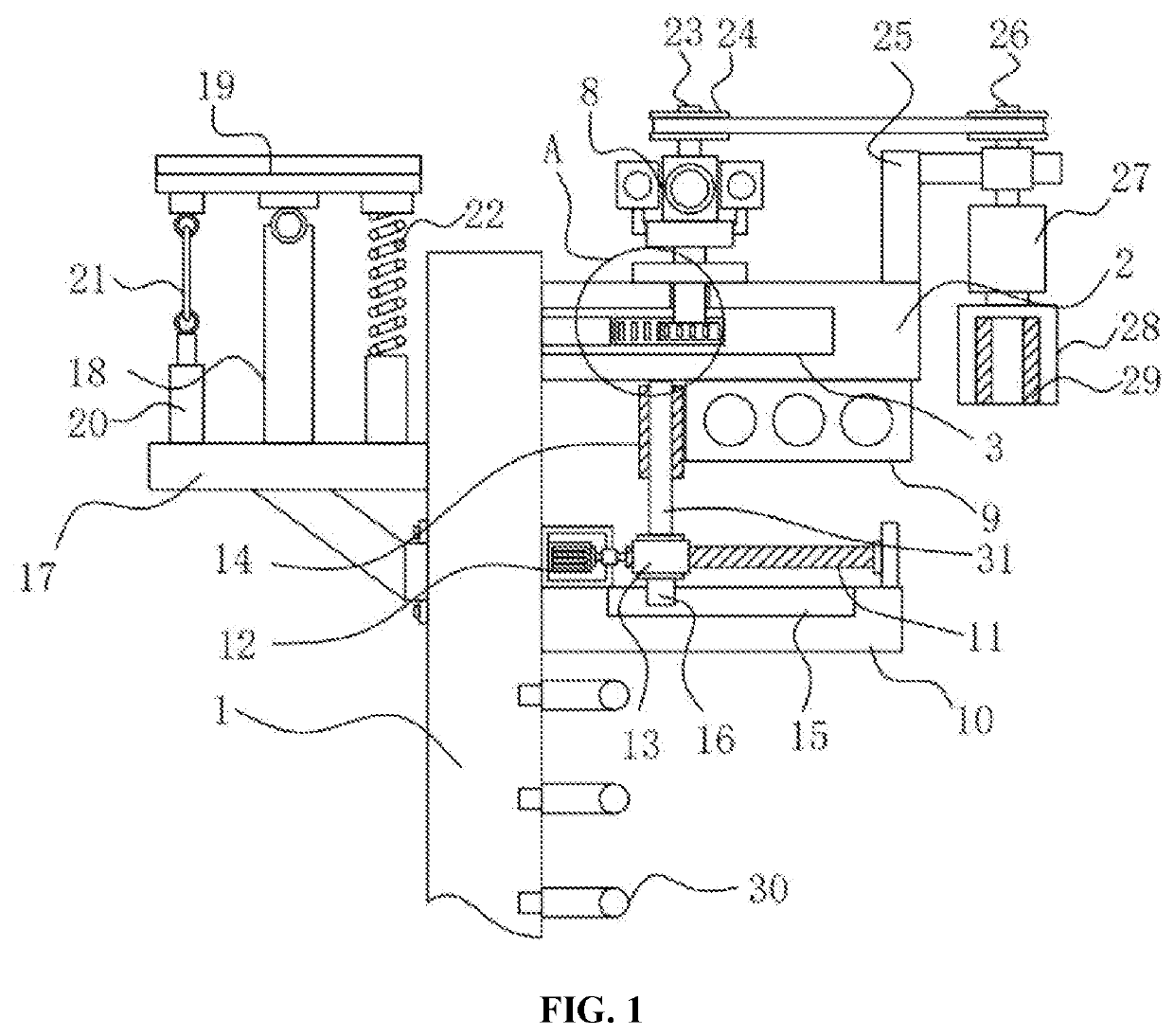
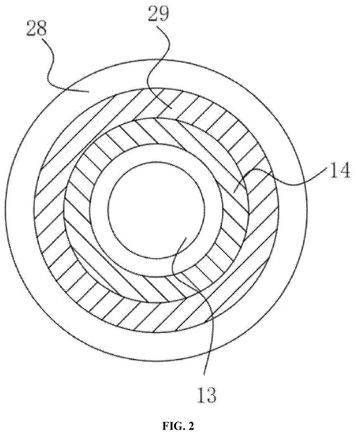
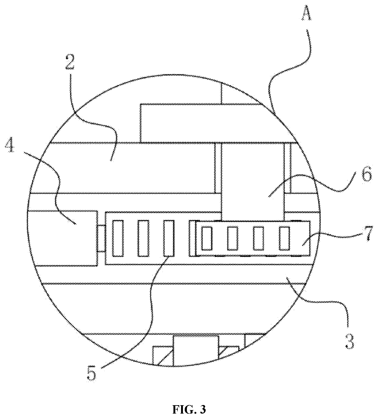
[0025]Referring to FIG. 1, FIG. 2 and FIG. 3, FIG. 1 is a structural schematic diagram of a preferred embodiment of a vehicle-road cooperation street lamp for an urban road provided by the present disclosure; FIG. 2 is an upward structural schematic diagram of a cleaning sleeve as (28) shown in FIG. 1; and FIG. 3 is an enlarged structural schematic diagram of part A in FIG. 1. The vehicle-road cooperation street lamp for an urban road comprises a vehicle-road cooperation street lamp body 1, wherein a first supporting plate 2 is transversely arranged on the front side of the top of the vehicle-road cooperation street lamp body 1, a transmission cavity 3 is transversely formed in the first supporting plate 2, the arranged first supporting plate 2 can play a role in supporting, and transmission can be performed in the transmission cavity 3.

[0026]A first electric...


PUM


Abstract

Provided is a vehicle-road cooperation street lamp for an urban road. The vehicle-road cooperation street lamp for an urban road comprises a vehicle-road cooperation street lamp body, wherein a first supporting plate is transversely arranged on the front side of the top of the vehicle-road cooperation street lamp body, a transmission cavity is transversely formed in the first supporting plate, a first electric telescopic rod is transversely arranged in the inner cavity of the transmission cavity and located on the outer wall of the vehicle-road cooperation street lamp body, and a rack plate is transversely arranged on the front side of the first electric telescopic rod and located in the transmission cavity.

Description

CROSS REFERENCE TO RELATED APPLICATION(S)[0001]This patent application claims the benefit and priority of Chinese Patent Application No. 202011469155.1, filed on Dec. 14, 2020, the disclosure of which is incorporated by reference herein in its entirety as part of the present application.TECHNICAL FIELD[0002]The present disclosure relates to the field of vehicle-road cooperation street lamps, in particular to a vehicle-road cooperation street lamp for an urban road.BACKGROUND ART[0003]According to vehicle-road cooperation, advanced wireless communication, new-generation Internet, and other technologies are adopted, vehicle-vehicle and vehicle-road dynamic real-time information interaction are comprehensively implemented, vehicle active safety control and road cooperation management are carried out on the basis of full-space-time dynamic traffic information collection and fusion, effective cooperation of people, vehicles and roads is fully achieved, traffic safety is guaranteed, and t...

Claims


Application Information

Patent Timeline
Patent Type & Authority Applications(United States)
IPC IPC(8): F21V21/15F21S8/08F21S9/03F21V17/12
CPCF21V21/15F21S8/08F21W2131/103F21V17/12F21S9/035F21V33/0052B08B1/002F16M13/02G08G1/0175H04N7/18H04N23/695Y02B20/72
Inventor ZHANG, XIZHENGLU, ZHANGYUWAN, QINYUAN, XIAOFANGWANG, ZEYU
Owner HUNAN INSTITUTE OF ENGINEERING
Why Eureka
Try Eureka