
Differential device

a technology of differential rings and gears, applied in the direction of gearing details, mechanical equipment, gearing gears, etc., can solve the problems of increased gear noise, unsatisfactory differential ring gear position accuracy, etc., to prevent the increase of gear noise, maintain the position accuracy of differential ring gears, and suppress differential ring gears

Active Publication Date: 2022-06-23
AISIN CORP
View PDF3 Cites 1 Cited by
  • Summary
  • Abstract
  • Description
  • Claims
  • Application Information

AI Technical Summary

Benefits of technology

The disclosed differential device has a satisfactory position accuracy of the differential ring gear after welding, which prevents a gear noise from increasing. This is achieved by welding the flange portion of the differential case and the fixed and supported portion of the differential ring gear at a different position from the abutting surfaces and the restricting portion. Solidification contraction after welding helps to keep the differential ring gear upright and maintain its position accuracy.

Problems solved by technology

There is a problem in which if a position accuracy of the differential ring gear with respect to the differential case is not satisfactory, the meshing in the differential ring gear is not satisfactory and the gear noise is increased.
Thus, the differential ring gear is easily inclined with the abutting portion on the inner peripheral side serving as a fulcrum, the position accuracy of the differential ring gear becomes unsatisfactory, and the gear noise is increased, which is a problem.

Method used


Image

  • Differential device
  • Differential device
  • Differential device

Examples


Embodiment Construction

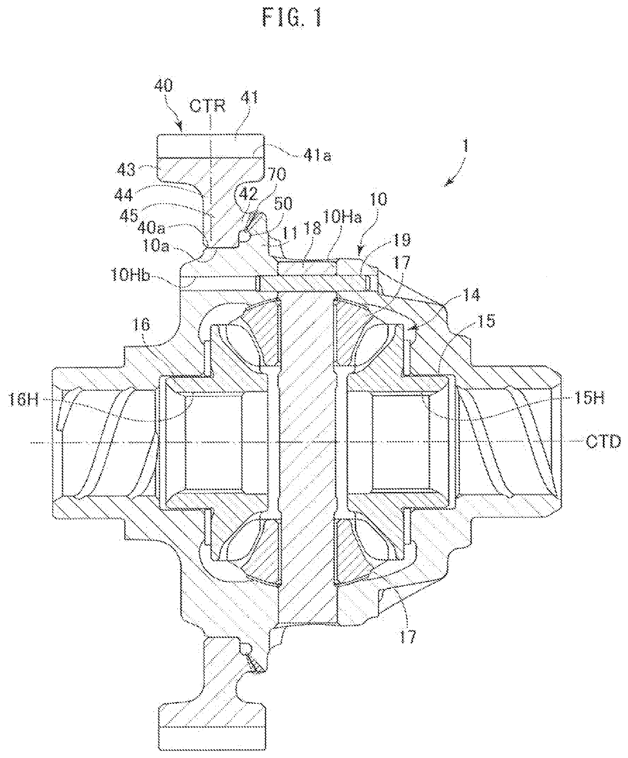
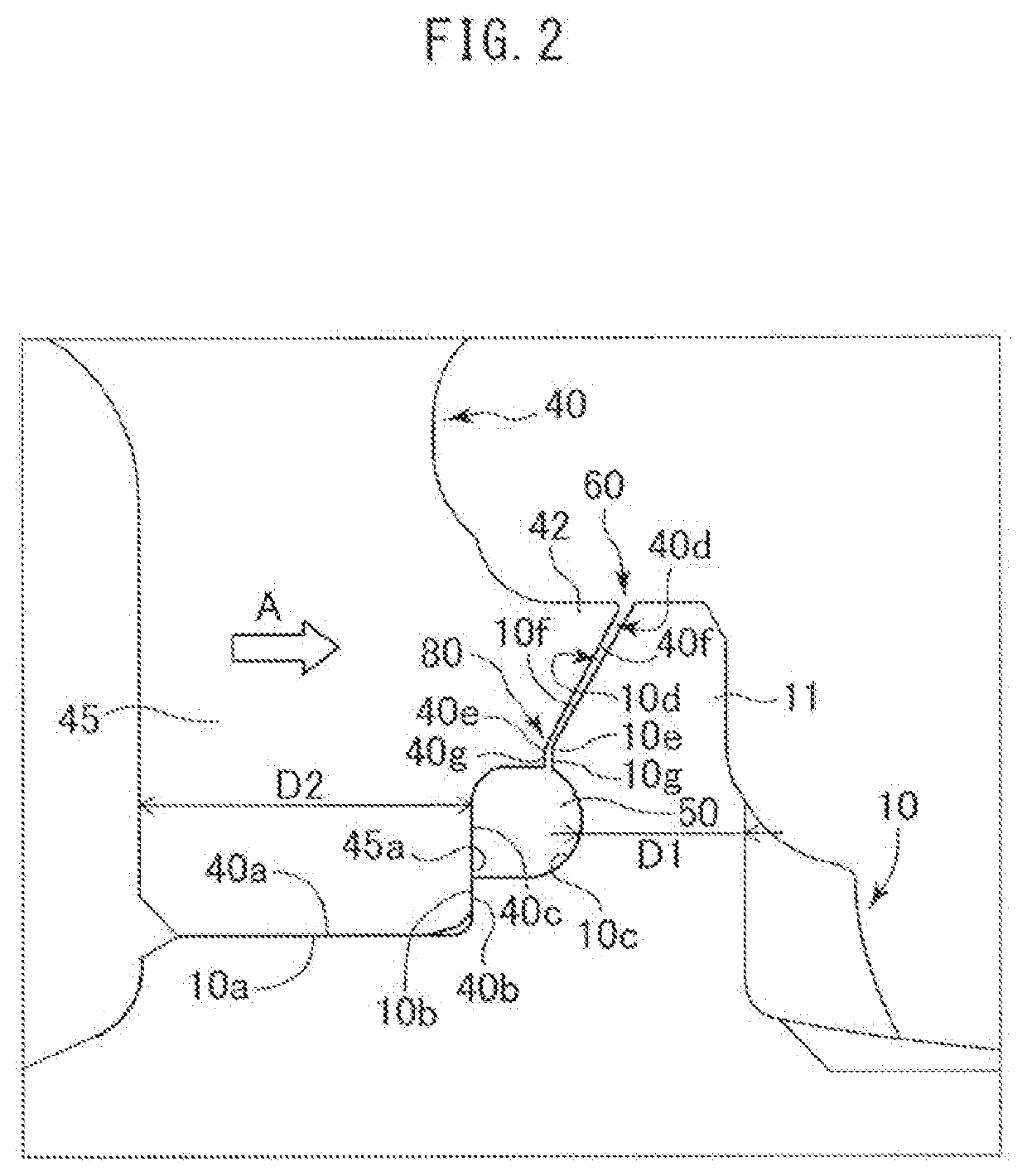
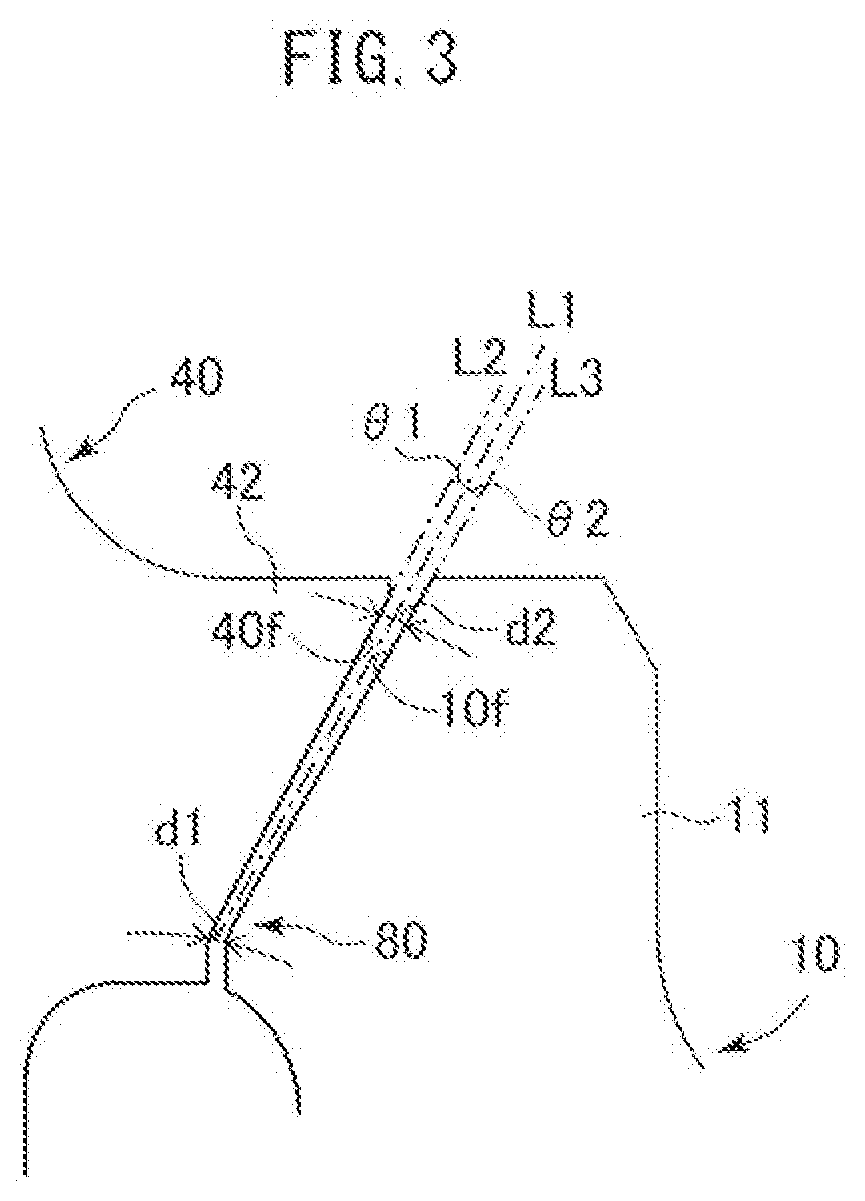
[0027]Hereinafter, a differential device according to an embodiment will be described with reference to FIGS. 1 to 6. FIG. 1 illustrates a sectional view of a differential device according to the embodiment. FIG. 2 illustrates an enlarged sectional view of an assembling portion of a differential case and a differential ring gear according to the embodiment. FIG. 3 illustrates an enlarged sectional view of a separation portion according to the embodiment. FIG. 4 illustrates an enlarged sectional view of the differential case and the differential ring gear during welding according to the embodiment. FIG. 5 illustrates an enlarged sectional view of a welding portion of the differential case and the differential ring gear after welding according to the embodiment. FIG. 6 illustrates a flowchart of a manufacturing process of the differential device according to the embodiment.

[0028][Overall Structure of Differential Device]

[0029]A differential device 1 according to the embodiment is prov...


PUM


Abstract

A differential device includes a differential case (10) that has a flange portion (11) and a differential ring gear (40) that has a tooth portion, a fixed and supported portion (45), and a coupling portion. The differential case (10) has a first abutting surface (10a) and a restricting portion (10b). The differential ring gear (40) has a second abutting surface (40a) and an abutting portion (40b). A welding portion that is formed by welding the flange portion (11) of the differential case (10) and the fixed and supported portion (45) of the differential ring gear (40) is disposed at a position that is different from an abutting part between the first abutting surface (10a) and the second abutting surface (40a) and an abutting part between the restricting portion (10b) and the abutting portion (40b).

Description

CROSS REFERENCE TO RELATED APPLICATIONS[0001]This application is a National Stage of International Application No. PCT / JP2018 / 031522, filed Aug. 27, 2018, claiming priority to Japanese Patent Application No. 2017-168088, filed Aug. 31, 2017.TECHNICAL FIELD[0002]The technique relates to a differential device installed in a vehicle etc.BACKGROUND ART[0003]Conventionally, a differential device is installed in a vehicle etc. so as to absorb a rotational difference between left and right wheels when turning or to absorb a rotational difference between front wheels and rear wheels, for example. In general, the differential device is configured to input a rotation output from a speed change mechanism to a differential ring gear, transmit the rotation from the differential ring gear to a differential case that houses a differential mechanism, and transmit the rotation to a pair of output members while absorbing a differential rotation of the output members with the differential mechanism.[0...

Claims


Application Information

Patent Timeline
Patent Type & Authority Applications(United States)
IPC IPC(8): F16H48/40F16H57/00
CPCF16H48/40F16H2048/385F16H57/0006F16H48/08F16H57/08F16H2048/382
Inventor ONO, HIROYUKISUZUKI, YUSUKE
Owner AISIN CORP
Learn More