Display Apparatus Realizing a Narrow Viewing Angle

a technology of viewing angle and display device, which is applied in the direction of electrical devices, semiconductor devices, diodes, etc., can solve problems such as moire phenomenon, and achieve the effects of narrow viewing angle, preventing moire phenomenon, and improving the frontal luminance of each emission region

Pending Publication Date: 2022-06-23
LG DISPLAY CO LTD
View PDF0 Cites 0 Cited by
  • Summary
  • Abstract
  • Description
  • Claims
  • Application Information

AI Technical Summary

Benefits of technology

The invention provides a display with a narrow viewing angle and no moire phenomenon. It also improves the brightness of each emission region in front of the display.

Problems solved by technology

However, in the display apparatus, moire phenomenon may occur due to the light-blocking pattern.

Method used


Image

  • Display Apparatus Realizing a Narrow Viewing Angle
  • Display Apparatus Realizing a Narrow Viewing Angle
  • Display Apparatus Realizing a Narrow Viewing Angle

Examples


embodiment

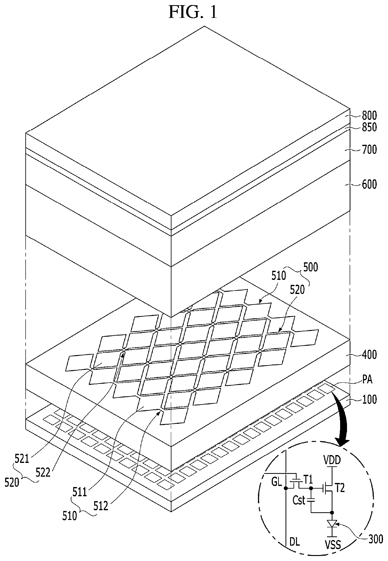
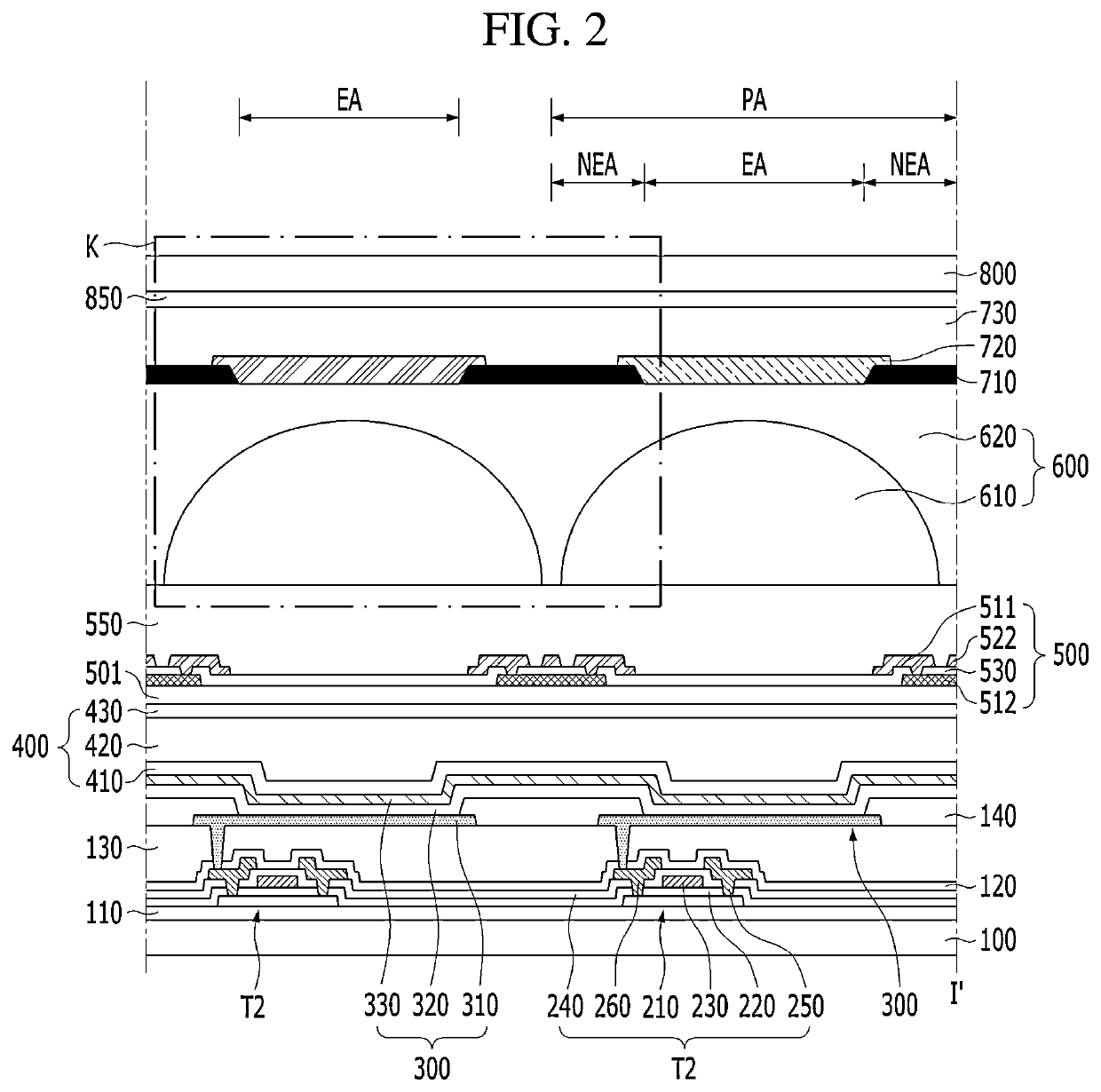
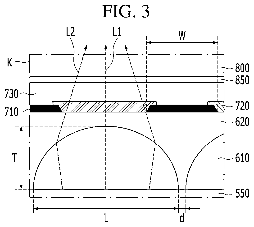
[0025]FIG. 1 is a view schematically showing a display apparatus according to an embodiment of the present disclosure. FIG. 2 is a view showing a cross-section of a pixel area in the display apparatus according to the embodiment of the present disclosure. FIG. 3 is an enlarged view of K region in FIG. 2 according to an embodiment of the present disclosure.

[0026]Referring to FIGS. 1 to 3, the display apparatus according to embodiment of the present disclosure may include a device substrate 100. The device substrate 100 may include an insulating material. For example, the device substrate 100 may include glass or plastic.

[0027]Signal wires GL, DL, VDD and VSS may be disposed on the device substrate 100. The signal wires GL, DL, VDD and VSS may transmit various signals to realize an image. For example, the signal wires GL, DL, VDD and VSS may include a gate line GL applying a gate signal, a data line DL applying a data signal, and a power voltage supply line VDD and VSS supplying a pow...


PUM

PropertyMeasurementUnit
aspect ratioaaaaaaaaaa
transmittanceaaaaaaaaaa
aspect ratioaaaaaaaaaa

Abstract

A display apparatus realizing a narrow viewing angle is provided. The display apparatus may include a light-emitting device on an emission region of a device substrate. A touch structure and a lens may be disposed on an encapsulating element covering the light-emitting device. The lens may be disposed on the emission region. A color filter may be disposed on the touch structure and the lens. Thus, in the display apparatus, Moire phenomenon may be prevented or at least reduced.

Description

CROSS-REFERENCE TO RELATED APPLICATION[0001]This application claims the benefit of Republic of Korea Patent Application No. 10-2020-0178238 filed on Dec. 18, 2020, which is hereby incorporated by reference in its entirety.BACKGROUND OF THE INVENTIONField of the Invention[0002]The present disclosure relates to a display apparatus realizing a narrow viewing angle using a touch structure.Discussion of the Related Art[0003]Generally, an electronic appliance, such as a monitor, a television (TV), a laptop computer, and a digital camera, includes a display apparatus capable of realizing an image. For example, the display apparatus may include light-emitting devices. Each of the light-emitting devices may emit light displaying a specific color. For example, each of the light-emitting devices may include a light-emitting layer disposed between a first emission electrode and a second emission electrode.[0004]The display apparatus may realize the narrow viewing angle so that the image provide...

Claims


Application Information

Patent Timeline
Patent Type & Authority Applications(United States)
IPC IPC(8): H01L27/32H01L51/52
CPCH01L27/3246H01L27/323H01L51/5284H01L51/5237H01L51/5275H01L27/322H10K59/38H10K59/40H10K59/122H10K59/12H10K59/8792H10K59/879H10K59/8722H10K50/84H10K50/858H10K50/865
Inventor KIM, SUNG WOOLEE, YOUNG BOKJANG, JU HOONYOON, A RAKIM, DONG YEONKANG, HOON
Owner LG DISPLAY CO LTD
Why Eureka
Try Eureka