Photoetching method

A technology of lithography and lithography equipment, applied in the field of lithography, can solve problems such as lithography pattern distortion, and achieve the effect of reducing the degree of distortion

Active Publication Date: 2012-06-06
SEMICON MFG INT (SHANGHAI) CORP +1
View PDF5 Cites 6 Cited by
  • Summary
  • Abstract
  • Description
  • Claims
  • Application Information

AI Technical Summary

Problems solved by technology

In conclusion, in the photolithography method of the prior art, even after OPC processing, the photolithographic pattern still has a certain degree of distortion compared with the original target pattern

Method used


Image

  • Photoetching method
  • Photoetching method
  • Photoetching method

Examples


Embodiment Construction

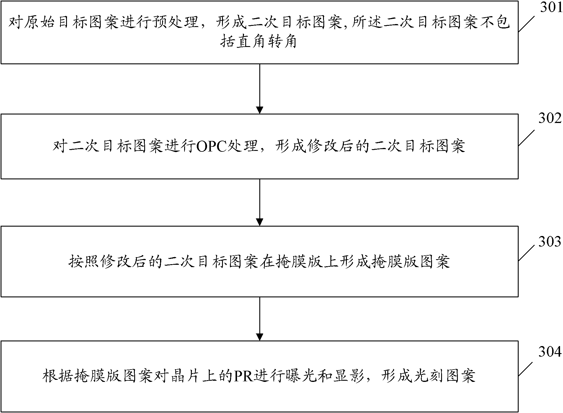
[0036] In order to make the object, technical solution and advantages of the present invention clearer, the solutions of the present invention will be further described in detail below with reference to the accompanying drawings and examples.
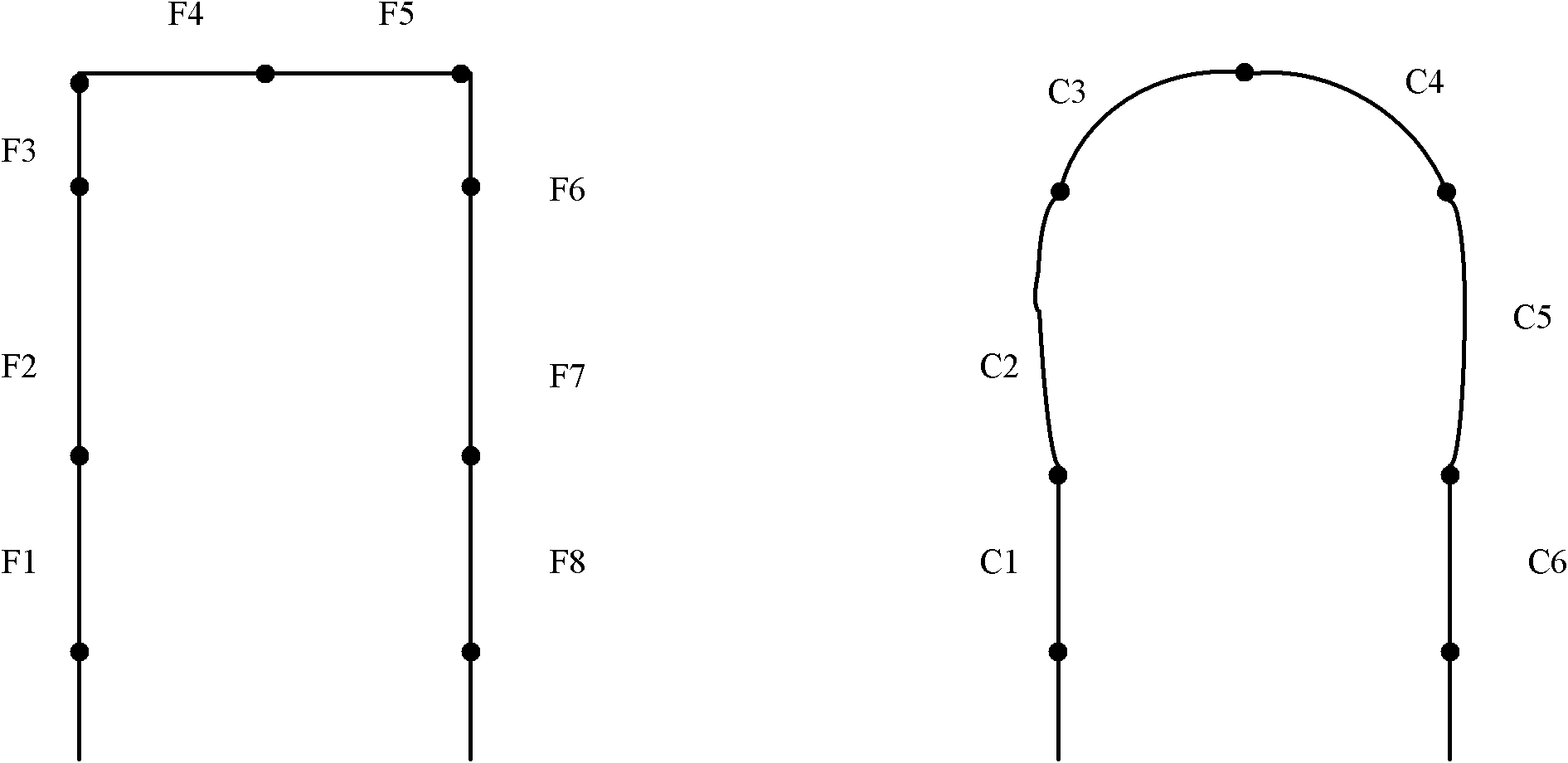
[0037] The core idea of ​​the present invention is: in the prior art, OPC processing is directly performed on the original target pattern, and the processed pattern is used as a mask pattern. Since the right-angle corner feature in the original target pattern is strengthened during OPC processing, the resulting The additional effect is exactly that the graphics near the right-angled corner may be distorted; and in the present invention, the original target pattern is first preprocessed to form a secondary target pattern that does not include the right-angled corner, and then the secondary target pattern is OPC processed. Since the secondary target pattern does not have the right-angle corner feature, the problem of distortion of the grap...


PUM


Abstract

The invention discloses a photoetchning method, which comprises: pre-treating an original target pattern so as to form a secondary target pattern, which excludes a right-angled corner; conducting OPC (optical proximity correction) treatment to the secondary target pattern so as to form a revised secondary target pattern; forming a mask pattern on a mask according to the revised secondary target pattern; subjecting the PR (photoresist) on a wafer to exposure and development based on the mask pattern, thus forming a photoetching pattern. Employment of the method provided in the invention can reduce the distortion degree of a photoetching pattern.

Description

technical field [0001] The invention relates to the field of semiconductor manufacturing, in particular to a photolithography method. Background technique [0002] With the development of the semiconductor manufacturing process, the semiconductor chip develops toward a high integration level, and the higher the integration level of the semiconductor chip, the smaller the critical dimension (CD) of the semiconductor device. [0003] In the semiconductor manufacturing process, one of the important processes is photolithography. Photolithography is the process of transferring the pattern on the mask to the photolithography pattern on the wafer. Therefore, the quality of photolithography will directly affect the final formed chip. performance. [0004] However, in practical applications, optical proximity effects (OPE) are likely to occur when exposing high-density mask patterns for pattern transfer. The main manifestations of OPE are: the right-angled corners of the lithograp...

Claims


Application Information

Patent Timeline
Patent Type & Authority Applications(China)
IPC IPC(8): G03F7/00G03F7/20
Inventor 王伟斌王辉
Owner SEMICON MFG INT (SHANGHAI) CORP
Why Eureka
Try Eureka