Quick-release anchoring apparatus with self-mounted anchor member

Active Publication Date: 2022-06-30
ZIMMERMAN ISRAEL HARRY
View PDF6 Cites 0 Cited by
  • Summary
  • Abstract
  • Description
  • Claims
  • Application Information

AI Technical Summary

Benefits of technology

[0007]A quick-release anchoring apparatus includes an anchor member formed of a non-porous resilient material. The anchor member includes a flexible base seal member having a seal member upper side, a seal member lower side, and a seal member peripheral edge defining an outer periphery of the seal member upper side and the seal member lower side. The seal member lower side is configured to engage an external reference surface and form a substantially airtight seal therewith that defines a controlled pressure zone, the controlled pressure zone being situated between the seal member lower side and the reference surface. The anchor member further includes a central anchor member stem extending upwardly from the seal member upper side. The anchor member stem includes a stem lower end disposed on the seal member upper side and a raised stem upper end. A first auxiliary component has a central opening through which the anchor member stem extends. The anchor member stem includes a stem mounting portion configured for rigidly self-mounting the anchor member to the first auxiliary component central opening without any discrete retainers or fasteners, the stem mounting portion being the sole component that attaches the anchor member to the first auxiliary component. A vent port extends through the anchor member. The vent port has a lower end disposed on the seal member lower side in fluid communication with the controlled pressure zone and an upper end disposed on the stem upper end in fluid communication with an area of

Problems solved by technology

Attempts to pull the suction cup away from the reference surface will only increase the size of the volumetric cavity and further decrease the air pressure therein.
Because the base seal member is usually highly flexible and may have little or no concavity, its elastic rebound forces may be relatively weak and generally insufficient to ove

Method used


Image

  • Quick-release anchoring apparatus with self-mounted anchor member
  • Quick-release anchoring apparatus with self-mounted anchor member
  • Quick-release anchoring apparatus with self-mounted anchor member

Examples


Example

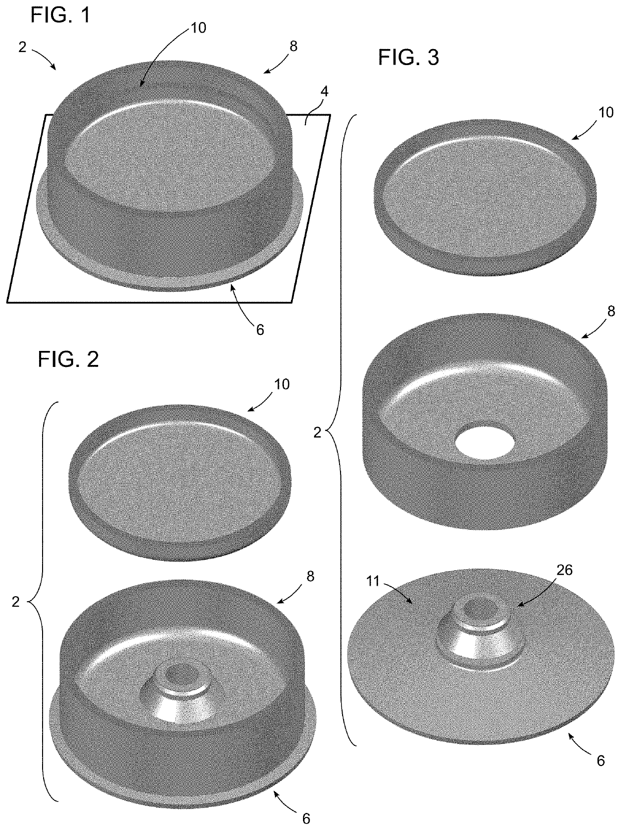
[0050]Turning now to the drawing figures, in which like reference numbers illustrate like structure in all of the several views, FIGS. 1-3 illustrate one possible embodiment a quick-release anchoring apparatus 2 that may be constructed in accordance with the present disclosure. The anchoring apparatus 2 may be used to provide a unique holder or carrier for one or more items or materials, and provides directional release and attachment capability that allows the apparatus to be secured to a reference surface 4 (FIG. 1) and quickly released therefrom as needed. In the illustrated embodiment, the anchoring apparatus 2 includes an anchor member 6, a first auxiliary component 8 to which the anchor member is rigidly self-mounted (FIG. 2), and a second auxiliary component 10 that is slidably mounted to the first auxiliary component (FIGS. 2-3). As described in more detail below, the first auxiliary component 8 serves as an anchor member carrier that may be fixedly mounted to the anchor mem...


PUM


Abstract

A quick-release anchoring apparatus includes an anchor member having a flexible base seal member that engages an external reference surface and forms a substantially airtight seal therewith to define a controlled pressure zone. The anchor member includes a central stem extending through an opening of the first auxiliary component. A mounting portion of the stem rigidly self-mounts the anchor member to the first auxiliary component opening. A vent port extends through the anchor member. A vent port upper end is centered within a stem landing zone on the stem upper end. A second auxiliary component is slidably mounted to the first auxiliary component and moves between a vent port closure position wherein the second auxiliary component engages the stem landing zone and blocks the vent port, a vent port open position wherein the second auxiliary component is out of engagement with the stem landing zone and unblocks the vent port.

Description

BACKGROUND1. Field[0001]The present disclosure relates to anchoring apparatus for releasably securing objects to surfaces. More particularly, the disclosure concerns anchoring apparatus with anchor members that adhere to surfaces by way of differential pressure when flexed. Still more particularly, the disclosure pertains to anchoring apparatus with quick-release differential pressure venting.2. Description of the Prior Art[0002]By way of background, anchoring apparatus that operate by way of differential pressure are known. Such apparatus often utilize anchor members such as suction cups and suction seal stabilizers. A suction cup typically includes a flexible base seal member configured as an elastomeric dome-shaped structure having a concave lower side and a relatively soft peripheral rim. In order to adhere the suction cup to a reference surface, the base seal member must be affirmatively flexed by pressing it against the reference surface with enough force to temporarily flatte...

Claims


Application Information

Patent Timeline
IPC IPC(8): F16M13/02F16B47/00
CPCF16M13/022F16B47/00F16M11/041A47G23/0225
Inventor ZIMMERMAN, ISRAEL HARRY
Owner ZIMMERMAN ISRAEL HARRY
Why Eureka
Try Eureka