Robot apparatus, method for controlling robot apparatus, and load compensation apparatus

US20220219321A1Pending Publication Date: 2022-07-14SONY CORP

Image

  • Robot apparatus, method for controlling robot apparatus, and load compensation apparatus
  • Robot apparatus, method for controlling robot apparatus, and load compensation apparatus
  • Robot apparatus, method for controlling robot apparatus, and load compensation apparatus

Examples


Embodiment Construction

[0037]An embodiment of a technique disclosed herein will be described below in detail with reference to the drawings.

A. Apparatus Configuration

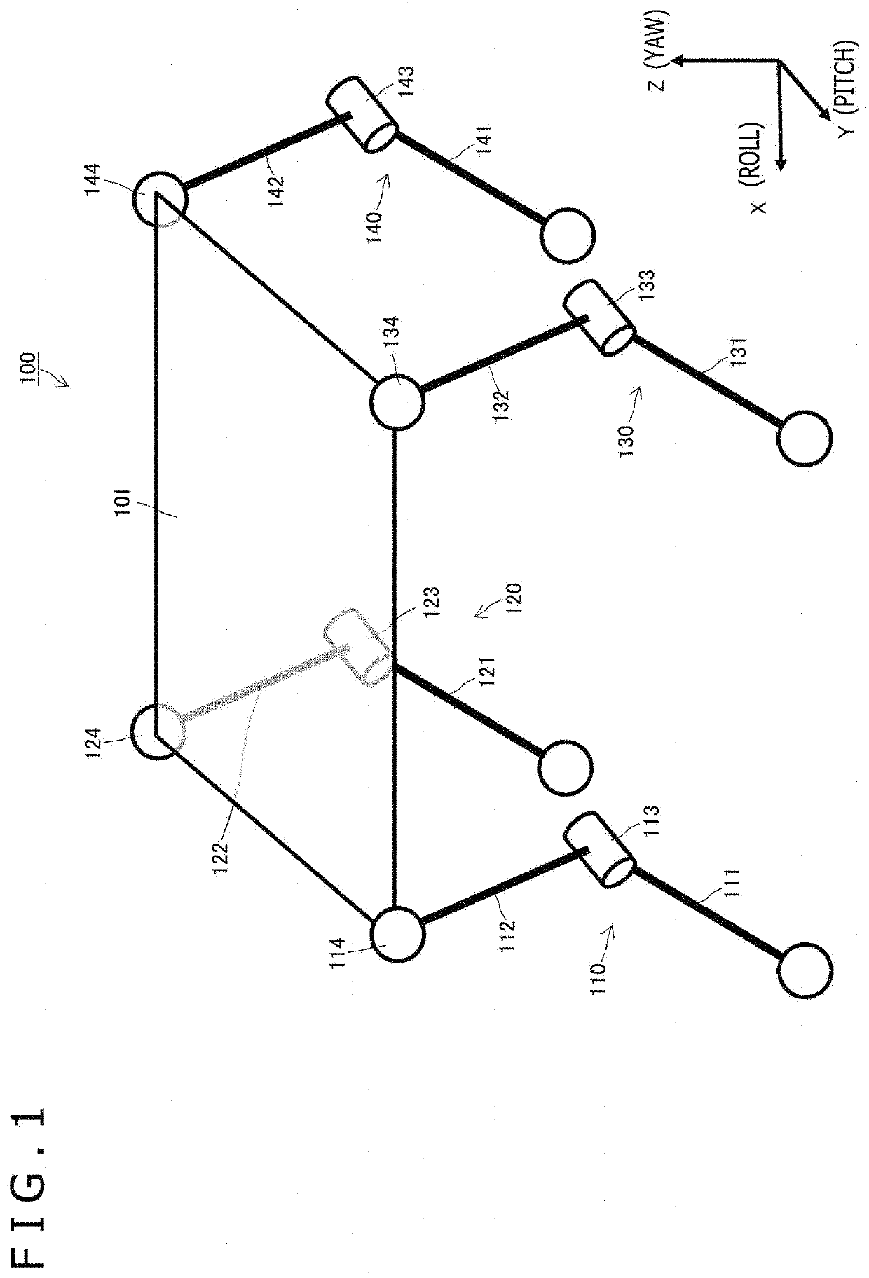
[0038]FIG. 1 schematically illustrates a configuration example of the degree of freedom of a robot apparatus 100 including a movable portion. The illustrated robot apparatus 100 includes a loading portion 101 on which luggage can be loaded, and four movable legs 110, 120, 130, and 140 coupled to respective four corners of the loading portion 101. The robot apparatus 100 is a walking robot that walks by synchronously operating the movable legs 110, 120, 130, and 140. Additionally, the robot apparatus 100 is assumed to be a luggage carriage robot carrying the luggage placed on the loading portion 101.

[0039]The movable leg 110 includes two links 111 and 112 and a joint portion 113 connecting the link 111 and the link 112. The other end (lower end) of the link 111 corresponds to a sole and is installed on a floor surface. Additionally, an upper e...


PUM


Abstract

There is provided a robot apparatus that includes a load compensation function dealing with a variation in load.The robot apparatus includes one or more movable portions, a load compensation section utilizing an elastic body to compensate for a load acting on the movable portion, and an initial displacement amount setting section applying, to the elastic body, an initial displacement amount corresponding to a desired position or posture of the movable portion. The initial displacement setting section includes an actuator displacing the elastic body by an initial displacement amount and locks the actuator with the elastic body remaining displaced by the initial displacement amount. The movable portion is a leg including a joint portion having a degree of rotational freedom around a pitch axis, and the initial displacement amount setting section sets the initial displacement amount on the basis of a toe force of the leg.

Description

TECHNICAL FIELD[0001]A technique disclosed herein relates to a robot apparatus including a movable portion such as a leg or an arm, a method for controlling the robot apparatus, and a load compensation apparatus.BACKGROUND ART[0002]In connection with the recent spread of automation techniques, robot apparatuses that include a movable portion such as a leg or an arm and that can be automatically operated have been utilized. The movable portion typically includes a multilink structure including a plurality of links connected together by a joint, and the movable portion is moved to any posture by driving the joint with use of an actuator such as a motor.[0003]Additionally, a load due to weights of the links constantly acts on the movable portion of the robot apparatus, and thus even in a case where the movable portion is to be kept stationary in a particular posture such as an upright posture, the actuator for driving the joint needs to be continuously operated, leading to power consum...

Claims


Application Information

Patent Timeline
14 Jul 2022
Publication
US20220219321A1
IPC
B25J9/16; B25J11/00; B62D57/032
CPC
B25J9/1638; B25J9/1641; B62D57/032; B25J11/008; B25J9/1633; B25J19/0016
Inventors
KAWANAMI, YASUNORI; KAMIKAWA, YASUHISA