Tire molding die and pneumatic tire

a technology of pneumatic tires and molding dies, which is applied in the direction of tires, domestic applications, other domestic articles, etc., can solve the problems of bending or breaking of blades, and achieve the effect of improving the durability of the sipe blades

Pending Publication Date: 2022-07-21
THE YOKOHAMA RUBBER CO LTD
View PDF0 Cites 0 Cited by
  • Summary
  • Abstract
  • Description
  • Claims
  • Application Information

AI Technical Summary

Benefits of technology

[0005]The present technology provides a tire molding die and a pneumatic tire that can improve durability of sipe blades.
[0014]The tire molding die and pneumatic tire according to an embodiment of the present technology have the effect of improving the durability of the sipe blades.

Problems solved by technology

However, various defects are likely to occur during vulcanization molding at division positions of sectors, and thus, some known tire molding dies are designed to eliminate such defects.
In particular, because the twist occurring in the blades is significant at or near the division position of sectors, the twist may cause failure such as bending or breakage of the blades.

Method used


Image

  • Tire molding die and pneumatic tire
  • Tire molding die and pneumatic tire
  • Tire molding die and pneumatic tire

Examples


embodiments

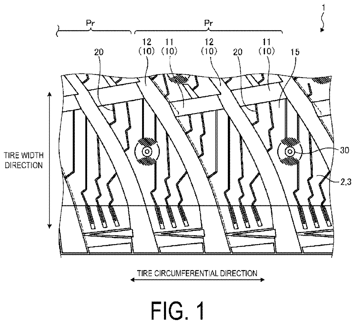
[0028]In the following description, the tire radial direction refers to a direction orthogonal to the rotation axis (not illustrated) of a pneumatic tire 1, the inner side in the tire radial direction refers to the side facing the rotation axis in the tire radial direction, and the outer side in the tire radial direction refers to the side away from the rotation axis in the tire radial direction. Moreover, the tire circumferential direction refers to the circumferential direction with the rotation axis as the central axis. Additionally, the tire width direction refers to a direction parallel with the rotation axis, the inner side in the tire width direction refers to a side toward the tire equatorial plane (tire equator line) CL in the tire width direction, and the outer side in the tire width direction refers to a side away from the tire equatorial plane CL in the tire width direction. The tire equatorial plane CL is a plane that is orthogonal to the rotation axis of the pneumatic ...

modified examples

[0064]Note that in the embodiment described above, the near sipe blade 121 and the original shape blade 122 are formed with identical shapes except for the maximum height, but may differ from each other in shapes other than the maximum height. FIG. 10 is a modified example of the tire molding die 100 according to an embodiment, and is a schematic plan view of the near sipe blade 121. FIG. 11 is a modified example of the tire molding die 100 according to an embodiment, and is a schematic plan view of the original shape blade 122. The near sipe blade 121 and the original shape blade 122 may be configured such that the number A1 of bend points 121a of the near sipe blade 121 differs from the number A2 of bend points 122a of the original shape blade 122. In this case, the relationship between the number A1 of bend points 121a of the near sipe blade 121 and the number A2 of the bend points 122a of the original shape blade 122 is preferably A21.

[0065]The number A1 of the bend points 121a ...

examples

[0071]FIG. 12 is a table showing results of performance evaluation tests of tire molding dies. In relation to the tire molding die 100 described above, the performance evaluation tests will be described that were conducted on a tire molding die of Conventional Example and the tire molding die 100 according to an embodiment of the present technology. The performance evaluation tests were conducted on the durability of the tire molding die.

[0072]The performance evaluation tests were conducted by evaluating the durability of the tire molding die when the pneumatic tire 1 having a tire nominal size of 205 / 55R16 94T, defined by JATMA, was vulcanization molded using the tire molding die. The method for evaluating the durability of the tire molding die includes, after vulcanization molding of the pneumatic tire 1, checking the near sipe blades 121, which are likely to be bent, for bending, repairing the near sipe blades 121 bent by 5° or more, and measuring the number of the near sipe blad...


PUM

PropertyMeasurementUnit
distanceaaaaaaaaaa
heightaaaaaaaaaa
heightaaaaaaaaaa

Abstract

A tire molding die includes sectors separated from one another in a tire circumferential direction, and sipe blades disposed on tread molding surfaces of the sectors, the sipe blades are disposed repeatedly in the tire circumferential direction in a repeating pattern corresponding to a predetermined arrangement pattern, and a near sipe blade that is included in sipe blades disposed in one of the sectors and that is a sipe blade closest to a division position between the sectors is more rigid than an original shape blade corresponding to the sipe blade provided in the repeating pattern differing from the repeating pattern including the near sipe blade at a position identical to a position of the near sipe blade in the repeating pattern including the near sipe blade.

Description

TECHNICAL FIELD[0001]The present technology relates to a tire molding die and a pneumatic tire.BACKGROUND ART[0002]Some known pneumatic tires are provided with so-called sipes, which are cuts formed in a tread portion, in order to improve performance on ice and snow, which is running performance on snowy roads and frozen road surfaces, and wet performance, which is running performance on wet road surfaces, and the like. For example, in studless tires, which are required to have running performance on icy and snowy road surfaces, a large number of sipes on the road contact surface of the tread portion are disposed. Additionally, the pneumatic tire is manufactured by vulcanization molding using a tire molding die divided into a plurality of sectors in the tire circumferential direction. However, various defects are likely to occur during vulcanization molding at division positions of sectors, and thus, some known tire molding dies are designed to eliminate such defects.[0003]For examp...

Claims


Application Information

Patent Timeline
Patent Type & Authority Applications(United States)
IPC IPC(8): B29D30/06
CPCB29D30/0606B29D2030/0613B29C33/424
Inventor KIDESAKI, TAKASHI
Owner THE YOKOHAMA RUBBER CO LTD
Why Eureka
Try Eureka