Needle-holding unit for a circular knitting machine

a technology of knitting machine and needle holding unit, which is applied in knitting, weft knitting, textiles and papermaking, etc., can solve the problems of not being able to reduce the value of the above-mentioned distance below a given value, and being unable to cast off the old stitch,

Pending Publication Date: 2022-07-21
SANTONI SPA
View PDF0 Cites 0 Cited by
  • Summary
  • Abstract
  • Description
  • Claims
  • Application Information

AI Technical Summary

Problems solved by technology

In the stitch forming point, the yarn must not be subjected to too high tensions since otherwise it would be likely to break.
In general, it is not possible to reduce the value of the aforesaid distance below a given value, since a given sinking is required for ensuring the correct formation of knitted stitches.
For instance, in high fineness, single needlebed machines it can be necessary for the sinking value to be at least of 0.7-0.8 mm, due to the minimum size that can be obtained for the hooks (or heads) of the needles: as a matter of fact, should the needles not sink below the holding-down plane—by means of the stitch cams—at least of such a value, it would not be possible to cast off the hooks the old stitch and it would not therefore be possible to correctly produce a knitted fabric.
Higher values of the pressure value (i.e. higher slopes of the stitch cam) can cause the butts of the moving needles to break, since the high inclination of the cam profile makes it difficult for the needle to slide in its seat due to the friction between needle and seat, which can lead to needle blocking and as a result to butt breaking in the stitch cam.
Moreover, the needle butts can sometimes bend and deviate from the vertical line as a result of the applied forces: this bending, if the slope of the stitch cam profile is high, can cause the butt to block inside the cam and therefore to break.
In a m

Method used


Image

  • Needle-holding unit for a circular knitting machine
  • Needle-holding unit for a circular knitting machine
  • Needle-holding unit for a circular knitting machine

Examples


Embodiment Construction

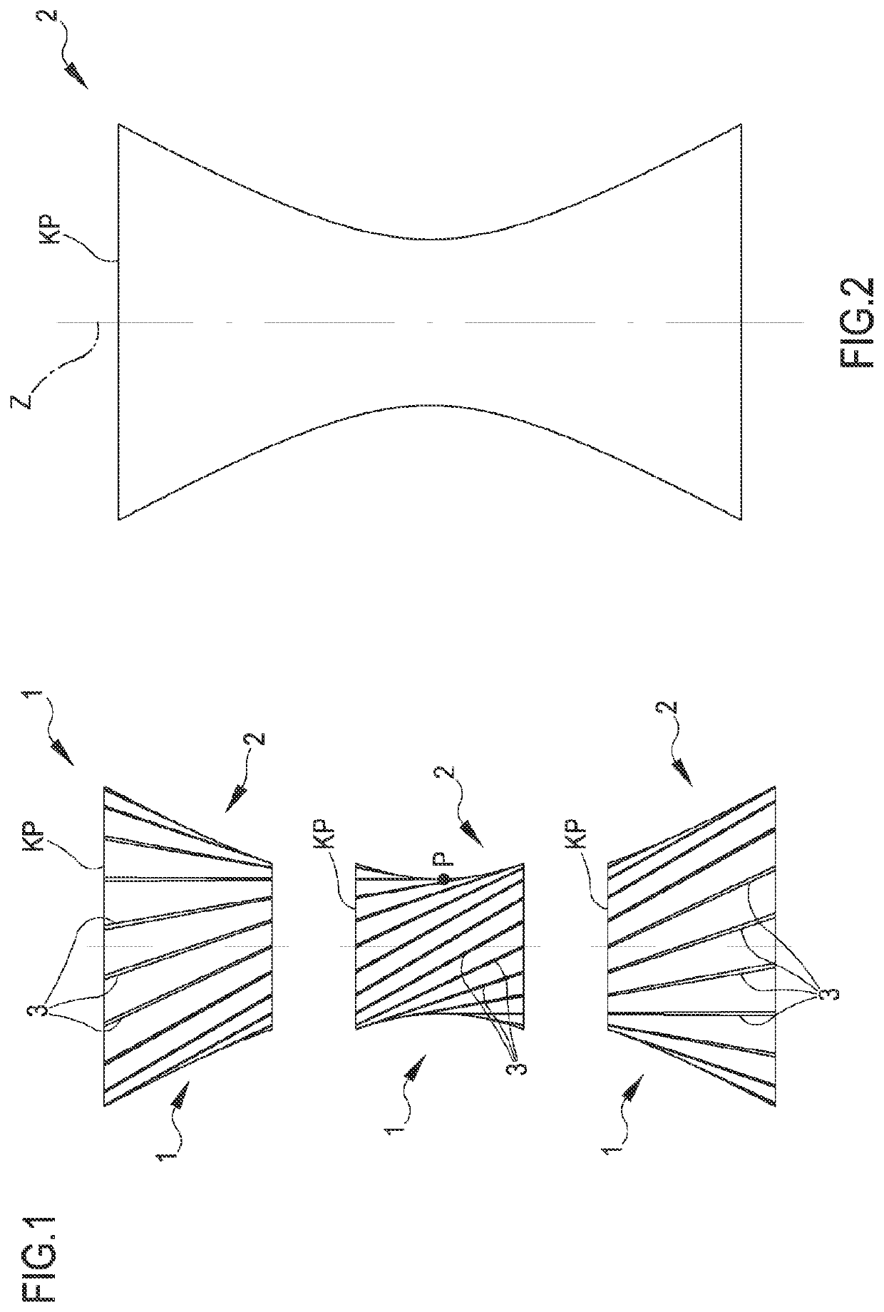
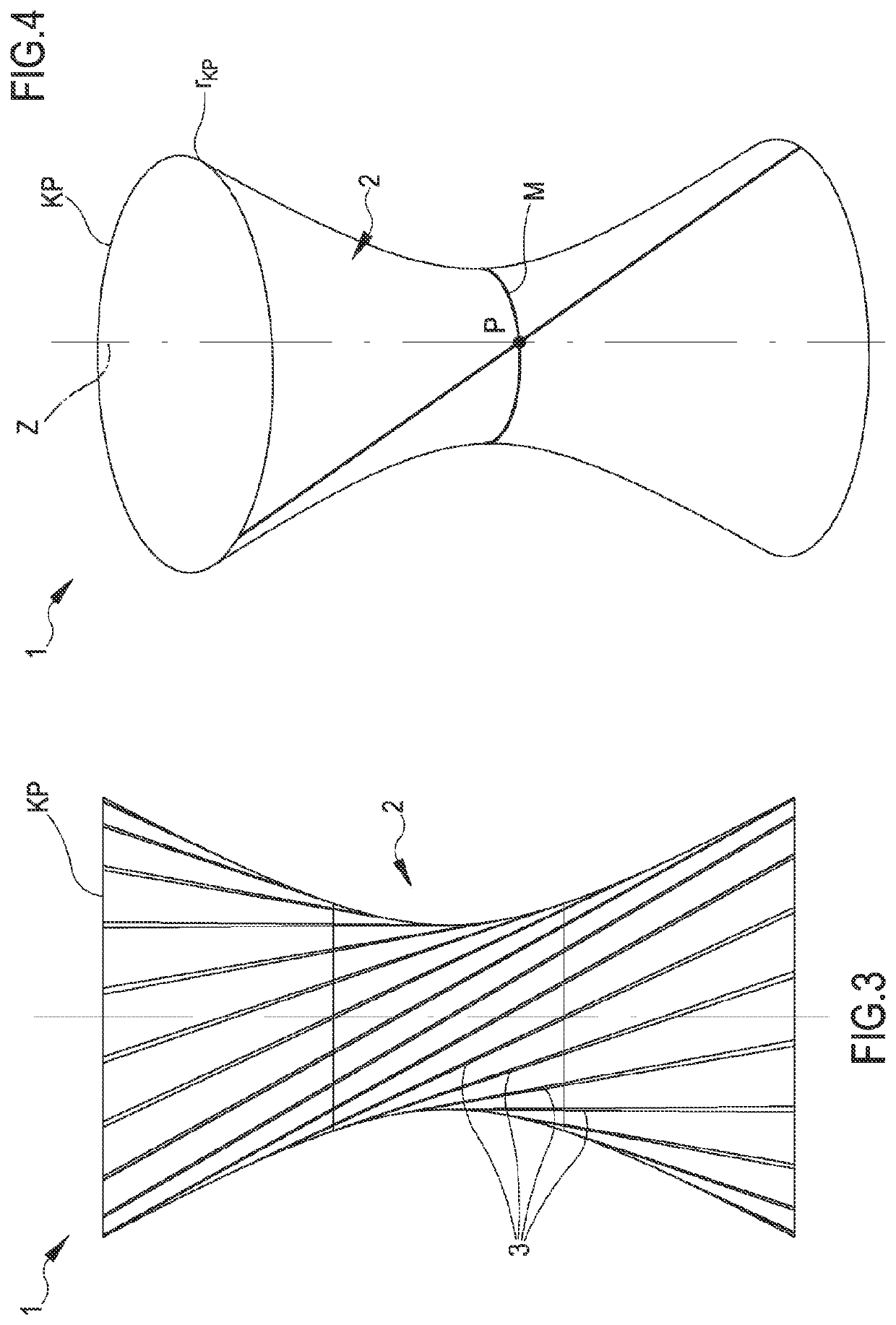
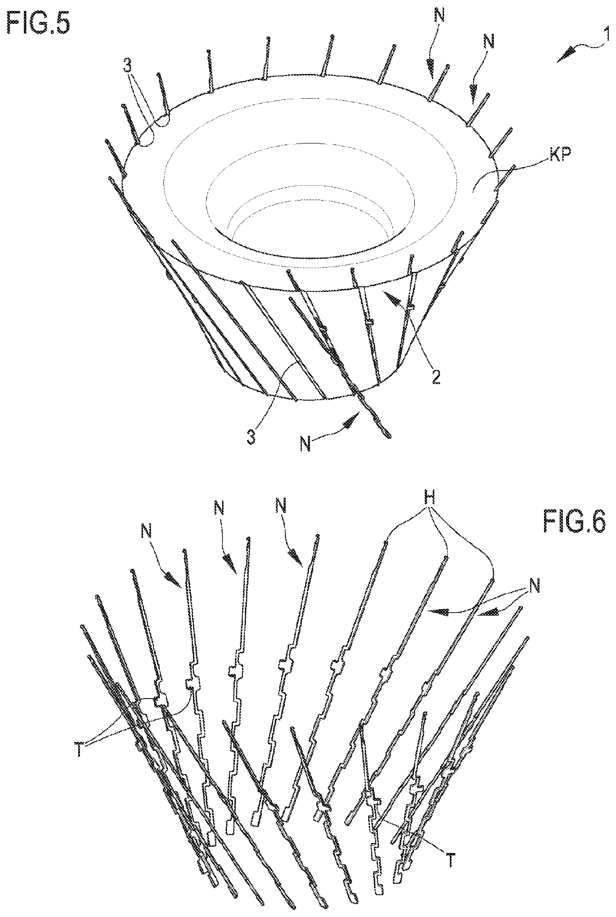
[0125]With reference to the mentioned figures, the numeral 1 globally designates a needle-holding unit for circular knitting machines according to the present invention. Generally, the same numeral is used for identical or similar elements, if applicable in their variants of embodiment.

[0126]The needle-holding unit 1 according to the present invention is designed to be introduced into a circular knitting machine for knitted items or seamless knitted items or for hosiery items. In further detail, the needle-holding unit 1 is designed to be mounted in a circular knitting machine comprising at least:[0127]a supporting structure (or frame);[0128]the needle-holding unit itself, turnably mounted to the frame so as to rotate around a central axis;[0129]a plurality of needles supported by the needle-holding unit and moving so as to produce a knitted fabric;[0130]a plurality of yarn feeding points or yarn “feeds”, in which the needles of the machine are supplied with yarn, the feeds being pl...


PUM


Abstract

A needle-holding unit for circular knitting machines has a structure shaped as a hollow solid of rotation developing around a central axis is configured for turning around said central axis and for supporting a plurality of needles moving so as to produce a knitted fabric. The needle-holding unit exhibits on an outer side at least one working surface, on which a plurality of needle seats is defined, which are placed beside one another and arranged around the central axis. Each of the needle seats movably houses at least a portion of at least one respective needle which can be actuated with an alternate motion along the respective needle seat with a motion of extraction and a motion of return, in order to produce knitted fabric. Each needle seat has an inclined longitudinal development with respect to the central axis. The working surface has a shape as a surface of rotation obtained through the rotation of the inclined needle seats around the central axis, and in particular the working surface is a non-cylindrical, non-conical three-dimensional surface.

Description

FIELD OF THE INVENTION[0001]The present invention relates to a needle-holding unit for a circular knitting machine and to a circular knitting machine comprising this unit.[0002]In particular, the present invention relates to a needle-holding cylinder or a needle-holding plate designed to be introduced into a knitting machine and characterized by a specific structure of its seats apt to house the needles of the knitting machine. The present invention can further relate to a circular knitting machine comprising a needle-holding unit, having a specific structure, and further components such as control units, needles, etc.[0003]The present invention falls into the technical field of circular knitting machines for knitted items, seamless knitted items, hosiery items and the like.[0004]In the present text the words “knitting machine” generally means a circular knitting machines apt to manufacture knitted items and provided with at least one needle-holding unit, i.e. with a needle-holding ...

Claims


Application Information

Patent Timeline
IPC IPC(8): D04B15/14D04B15/32
CPCD04B15/14D04B15/32D04B15/10
Inventor RIZZI, STEFANOANDREOLI, MARCOLONATI, ANDREA
Owner SANTONI SPA
Why Eureka
Try Eureka