Supercharge Your Innovation With Domain-Expert AI Agents!

Method and apparatus for radio link flow control

Pending Publication Date: 2022-07-21
LENOVO (BEIJING) CO LTD
View PDF0 Cites 1 Cited by
  • Summary
  • Abstract
  • Description
  • Claims
  • Application Information

AI Technical Summary

Benefits of technology

The present patent provides a method and apparatus for configuring and indicating congestion on a communication device. The technical effect is to improve communication efficiency and utilize network resources efficiently by providing a mechanism for communication devices to indicate congestion if the buffer size is equal to or greater than a predetermined threshold. This allows for timely adjustment of data transmission and avoidance of network congestion, thereby improving overall communication speed and quality.

Problems solved by technology

Nevertheless, an RN may experience congestion under certain conditions, and therefore a new solution is required to indicate congestion and control the congestion in the communication network.

Method used


Image

  • Method and apparatus for radio link flow control
  • Method and apparatus for radio link flow control
  • Method and apparatus for radio link flow control

Examples


Embodiment Construction

[0020]The detailed description of the appended drawings is intended as a description of preferred embodiments of the present disclosure and is not intended to represent the only form in which the present disclosure may be practiced. It should be understood that the same or equivalent functions may be accomplished by different embodiments that are intended to be encompassed within the spirit and scope of the present disclosure.

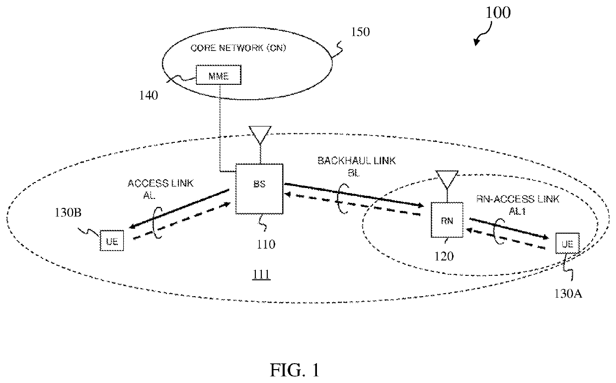
[0021]FIG. 1 illustrates a wireless communication system 100 according to some embodiments of the present disclosure.

[0022]Referring to FIG. 1, a wireless communication system 100 may include some nodes (e.g., BS 110 and RN 120) and some UEs (e.g., UE 130A and UE 130B). Although, for simplicity, merely two nodes are illustrated in FIG. 1, it is contemplated that wireless communication system 100 may also include more or fewer nodes in some other embodiments of the present disclosure. Although, for simplicity, merely two UEs are illustrated in FIG. 1, it is also...


PUM


Abstract

The present disclosure relates to methods and apparatuses. According to some embodiments of the disclosure, a method includes: receiving, at a communication device, a configuration message including a threshold to configure the communication device; and transmitting, from the communication device, a congestion indication if an occupied buffer size of the communication device is equal to or greater than the threshold.

Description

TECHNICAL FIELD[0001]The present disclosure generally relates to wireless communication technology, and more particularly to radio link flow control in a wireless communication system.BACKGROUND[0002]A wireless communication system may include a base station (hereinafter referred to as “BS”) which can be in communication with a user equipment (hereinafter referred to as “UE”). UE may include a mobile device (e.g., a cell phone, a tablet, a laptop, an internet-of-things (IoT) device, etc.). Quality of a communication link or channel between a BS and an UE may deteriorate due to various factors, for example but is not limited to, blockage by building(s), relatively long distance between the BS and the UE, etc. One of several solutions to resolve this problem may include deployment of relay nodes (hereinafter referred to as “RNs”) in the wireless communication system to enhance and / or expand coverage of the BS, as disclosed in the 3rd Generation Partnership Project (3GPP).[0003]A BS, w...

Claims


Application Information

Patent Timeline
IPC IPC(8): H04W28/02
CPCH04W28/0278H04W80/02H04W28/0284H04B7/26H04L47/30H04W84/047H04L47/267
Inventor WU, LIANHAILOHR, JOACHIMBASU MALLICK, PRATEEKSHI, JIEHAN, JINGWANG, HAIMING
Owner LENOVO (BEIJING) CO LTD
Features
  • R&D
  • Intellectual Property
  • Life Sciences
  • Materials
  • Tech Scout
  • Unparalleled Data Quality
  • Higher Quality Content
  • 60% Fewer Hallucinations
Learn More