Portable disc golf target

Pending Publication Date: 2022-08-11
ZAJAC THOMAS
View PDF3 Cites 0 Cited by
  • Summary
  • Abstract
  • Description
  • Claims
  • Application Information

AI Technical Summary

Benefits of technology

[0007]In preferred embodiments, the base might be detachable from the pole, lightweight, flat on both sides, and fairly thin, for easy storage. In preferred embodiments, the base is in the shape of a polygon having an odd number of sides (such as a pentagon, heptagon, nonagon, and so on), because the lack of symmetry may make the device less directionally oriented, and not more likely to be knocked over from any particular angle over another. Further, a polygon with flat sides rather than a rounded base such as a circular base may be preferable in most embodiments because this includes the added benefit of rolling on the ground less once knocked over. One preferred mechanism for attaching and detaching the base and pole might be a tapped aperture in the base and a threaded bottom end of the pole, such that the pole can be screwed into the base. In some preferred embodiments, the top of the pole is rounded. In some preferred embodiments, the pole may be painted with one or more stripes or section, such as to improve visibility or provide a target section of the pole to aim for while playing a game.
[0008]The invention may be ideal for use as sporting equipment for schools, as a portable, easily disassembled, easily assembled, and easily reassembled replacement disc golf target for the permanent fixture of a standard disc golf basket.
[0009]The invention is shaped and adapted to tilt over and fall easily when the pole is struck by a thrown projectile such as a golf disc. While the invented target may be initially viewed simply as an ‘easier’ designated target to use for discerning a hit from a miss, a

Problems solved by technology

This kind of game often had the drawback of players not being able to reliably determine whether the target had actually been struck, sometimes resulting in tiresome arguments, to the extent that the standard disc golf catching basket, a basket consisting of chains hanging in a parabolic shape and mounted on a metal pole that one might find in a park today, was invented in 1975.
However, not all parks or playgrounds inclu

Method used


Image

  • Portable disc golf target
  • Portable disc golf target
  • Portable disc golf target

Examples


Example

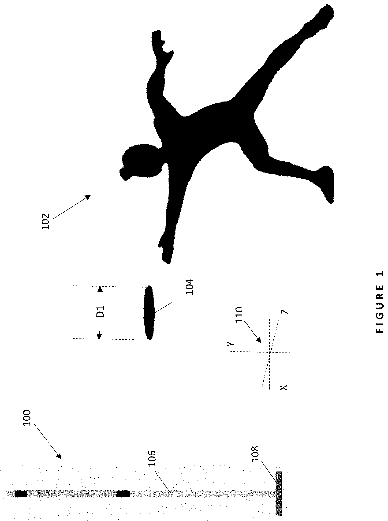
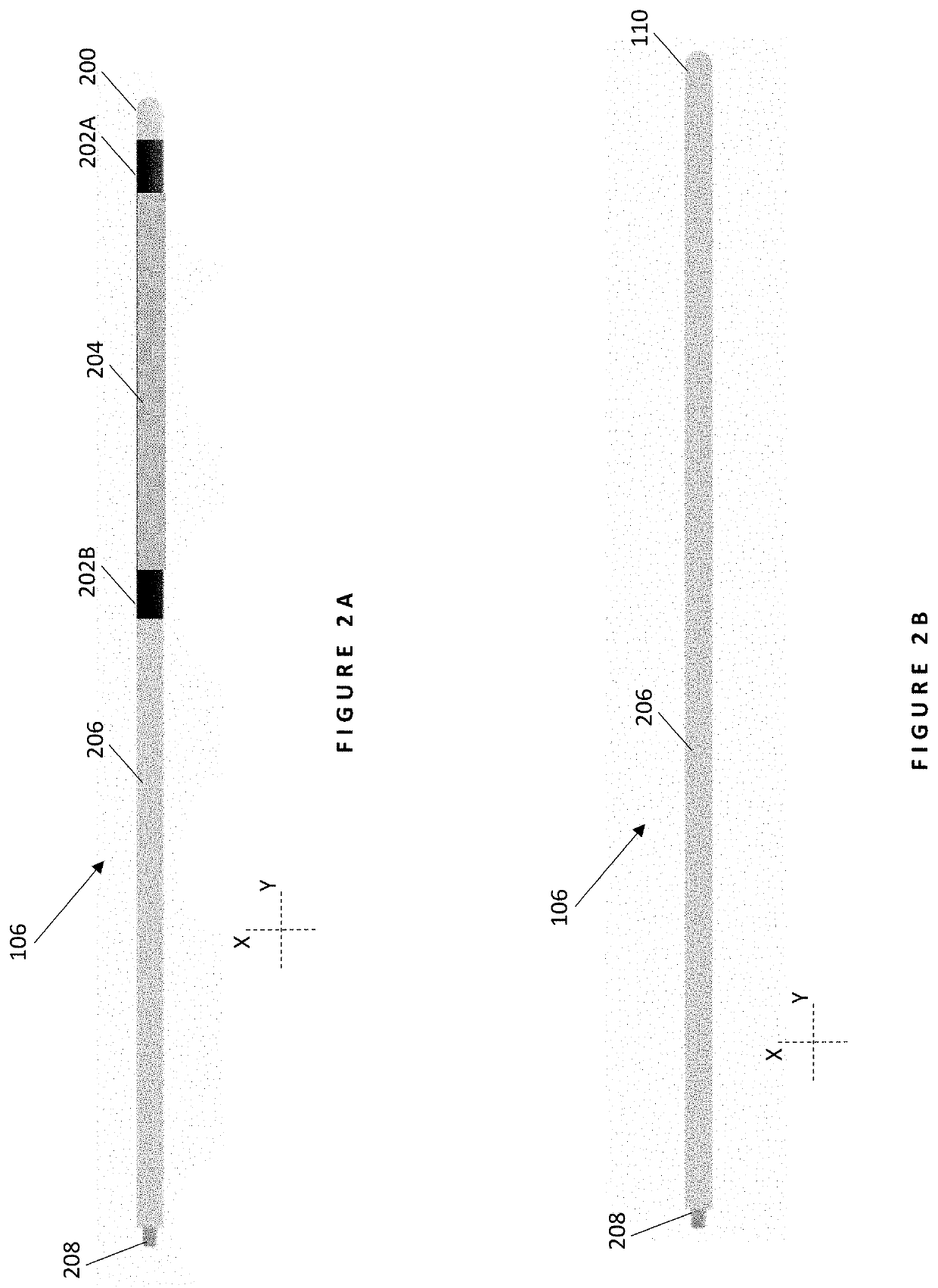
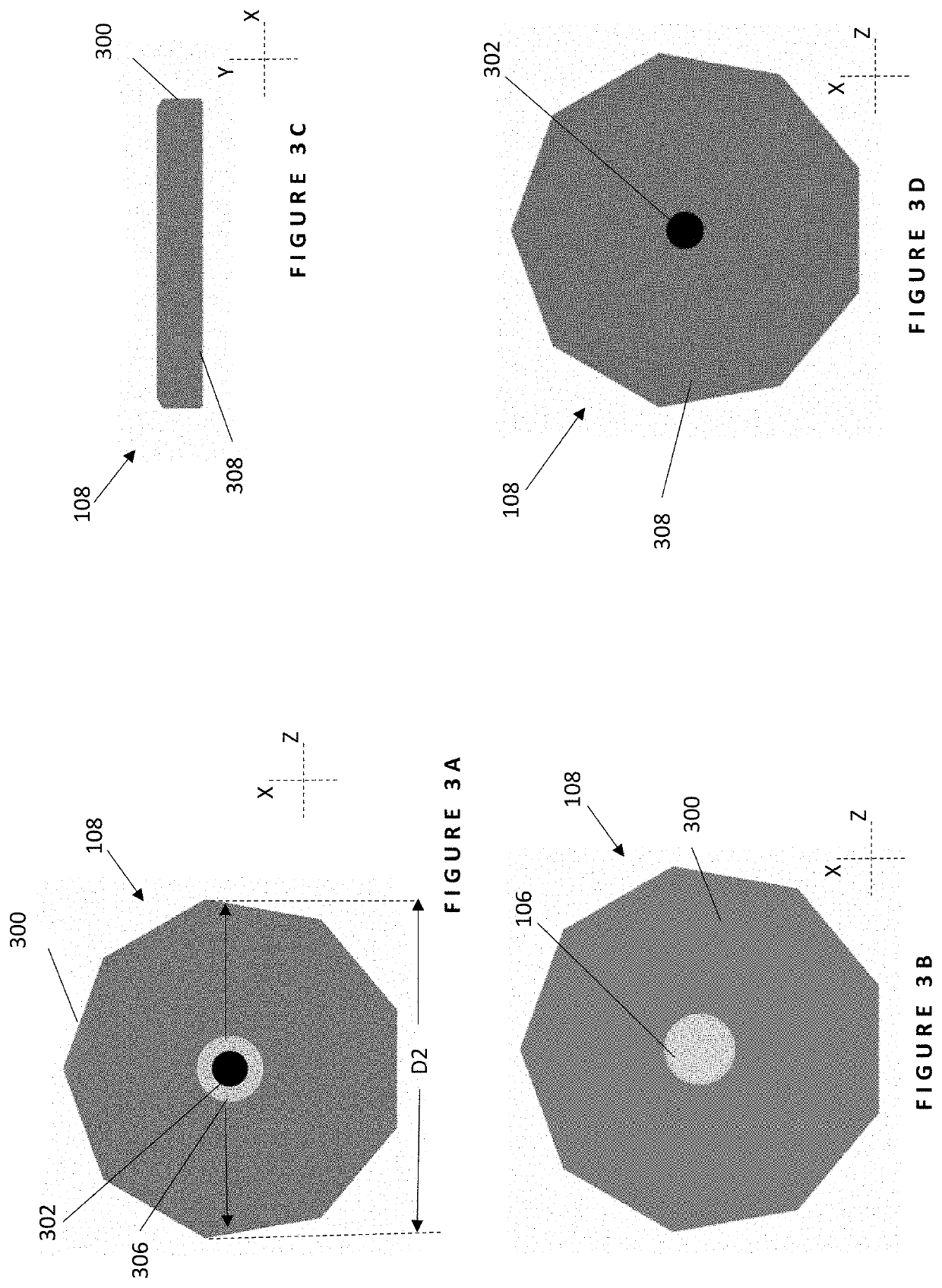
DETAILED DESCRIPTION OF DRAWINGS

[0022]In the following detailed description of the invention, numerous details, examples, and embodiments of the invention are described. However, it will be clear and apparent to one skilled in the art that the invention is not limited to the embodiments set forth and that the invention can be adapted for any of several applications.

[0023]It is to be understood that this invention is not limited to particular aspects of the present invention described, as such may, of course, vary. It is also to be understood that the terminology used herein is for the purpose of describing particular aspects only, and is not intended to be limiting, since the scope of the present invention will be limited only by the appended claims. Methods recited herein may be carried out in any order of the recited events which is logically possible, as well as the recited order of events.

[0024]Where a range of values is provided herein, it is understood that each intervening va...


PUM


Abstract

The invention includes a pole and a base that when detachably coupled stand upright for use as a knock-over target in the game of disc golf. The invention is shaped and adapted to fall over easily when the pole is struck. The pole may be plain or decorated with marking such as target sections or stripes, and the base is ideally lightweight, thin and relatively small, and shaped as a polygon with an odd number of sides. The invention provides disc golfers with a scoring target of exceedingly easier portability than prior art scoring target baskets and that in use improves the clarity of observers and judges as to whether a disc has made physical contact with the invention. The invention enables the game of disc golf to be more conveniently played at locations that are more difficult or infeasible to bring and position prior art basket targets.

Description

FIELD OF THE INVENTION[0001]The field of the invention relates to sporting equipment in general, and specifically to a lightweight pole with a base adapted to cause the pole to fall over easily when struck.BACKGROUND OF THE INVENTION[0002]The subject matter discussed in the background section should not be assumed to be prior art merely as a result of its mention in the background section. Similarly, a problem mentioned in the background section or associated with the subject matter of the background section should not be assumed to have been previously recognized in the prior art. The subject matter in the background section merely represents different approaches, which in and of themselves may also be inventions.[0003]It is generally accepted that the first game of “disc golf” was played in Bladworth, Saskatchewan, Canada, in 1927, with some elementary school children throwing tin lids into four-foot-wide circles drawn in sandy schoolyards. However, the game grew popular in the 19...

Claims


Application Information

Patent Timeline
IPC IPC(8): A63B67/06
CPCA63B67/06A63B2210/50A63B2071/0694A63B71/028A63B71/023
Inventor ZAJAC, THOMAS
Owner ZAJAC THOMAS
Why Eureka
Try Eureka