


Quick Research
Generate reliable direction feasibility study reports for your R&D in just a few steps.

Technical Q&A
Discover and master advanced knowledge NOW. Basics, ideas, possibilities, all at once.

Find Solutions
As an expert in R&D theories, this can generate solutions to your technical problems instantly.

Evaluate Feasibility
Analyze your overall solution with one click, know your potential R&D risks in advance.

Monitor Landscape
Get weekly tech updates, stay abreast of the latest tech innovations and key insights.
RFID tag roll
a technology of rfid tags and rolls, applied in the field of rfid tags, can solve the problems of easy application of achieve the effects of significantly reducing bending stress to the rfic mounted on the rfid tag, reducing bending stress, and solving the problem of cracking of the rfi
- Summary
- Abstract
- Description
- Claims
- Application Information
AI Technical Summary
Benefits of technology
Problems solved by technology
Method used
Image


Examples
first exemplary embodiment
[0023]FIG. 1A is a partial plan view in a state in which an RFID tag roll according to a first exemplary embodiment is spread. FIG. 1B is a front view of an RFID tag roll 301 according to the first exemplary embodiment.
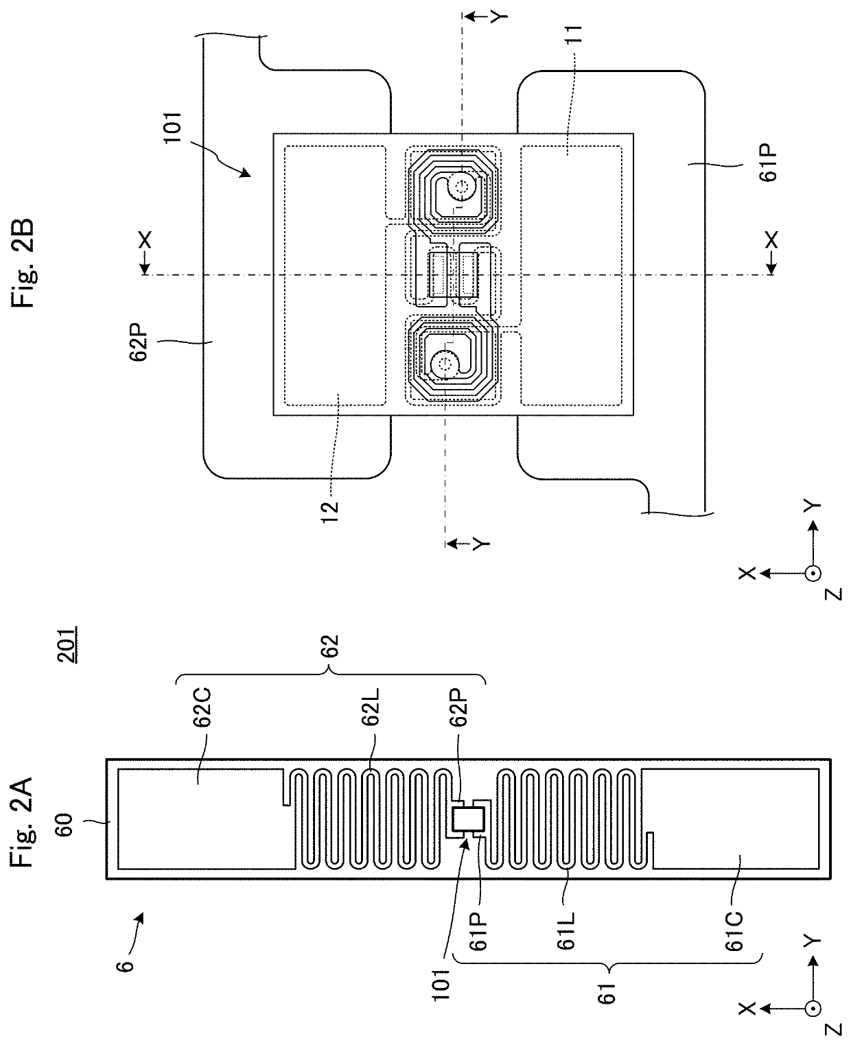
[0024]According to the exemplary aspect, the RFID tag roll 301, as shown in FIG. 1A, is configured by a large number of RFID tags 201 (e.g., a plurality of RFID tags) attached to a surface of strip-shaped paper 70. When this RFID tag roll 301 is manufactured, as shown in FIG. 1B, on the way to rewinding the paper from a roll 301S at a stage prior to mounting of an RFIC module, an RFIC module 101 is mounted in the antenna 6, and the paper is rolled into the RFID tag roll 301. Therefore, when expressed with the coordinate axes in the present embodiment, the winding direction (i.e., the length direction) of the RFID tag roll 301 is a Y direction as shown in FIG. 1B.
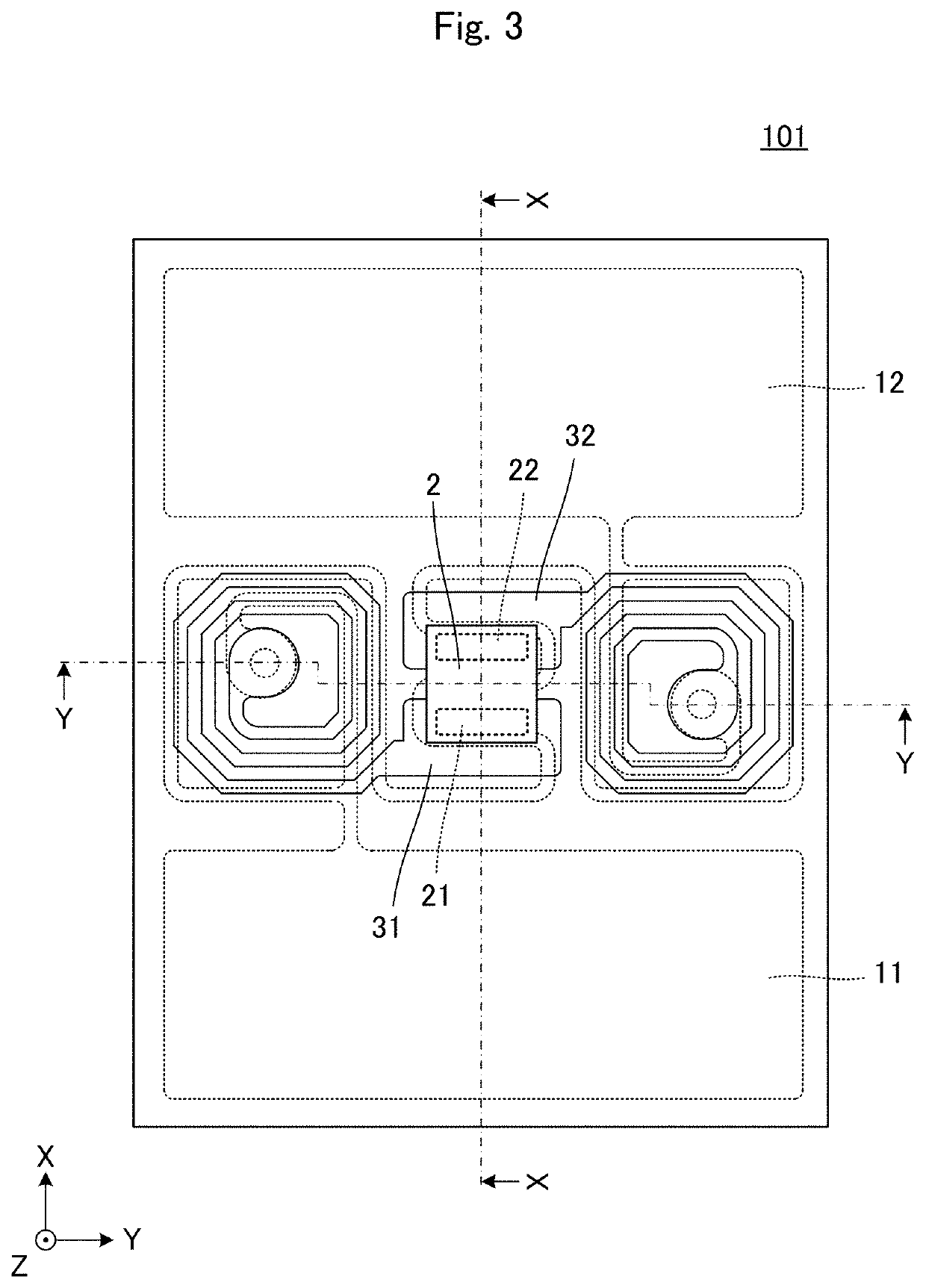
[0025]FIG. 2A is a plan view of an RFID tag 201 according to the first exemplary embodiment. FIG. 2B is an ...
second exemplary embodiment
[0049]In a second exemplary embodiment of the present disclosure, an example in which a relationship between a longitudinal direction of an RFID tag and an terminal electrode of an RFIC is different from the relationship in the first exemplary embodiment will be described.
[0050]FIG. 9 is a partial plan view in a state in which an RFID tag roll according to the second exemplary embodiment is spread. This RFID tag roll includes a large number of RFID tags 202 (e.g., a plurality of RFID tags) attached to a surface of strip-shaped paper 70. The winding direction (i.e., the length direction) of this RFID tag roll is the Y direction.
[0051]FIG. 10A is a plan view of an RFID tag 202 according to the second exemplary embodiment. FIG. 10B is an enlarged plan view of a portion on which an RFIC module 102 included in the RFID tag 202 is mounted.
[0052]The RFID tag 202 is configured by an antenna 6, and an RFIC module 102 coupled to the antenna 6. The antenna 6 is configured by an antenna base ma...
third exemplary embodiment
[0056]In a third exemplary embodiment, an example of an RFID tag roll in which RFID tags configured by an antenna and an RFIC mounted to the antenna are arranged will be described.
[0057]FIG. 11A is a plan view of an RFID tag 203 according to the third exemplary embodiment. FIG. 11B is an enlarged plan view of a portion on which an RFIC 2 included in the RFID tag 203 is mounted.
[0058]The RFID tag 203 is configured by an antenna 6, and an RFIC 2 connected to the antenna 6. The antenna 6 is configured by an antenna base material 60, and radiation conductors 61 and 62 provided on this antenna base material 60. Moreover, the antenna base material 60 is, for example, a polyethylene terephthalate (PET) film, and the radiation conductors 61 and 62 are, for example, patterns of Cu foil.
[0059]The radiation conductor 61 is configured by conductor patterns 61P, 61L, and 61C, and the radiation conductor 62 is similarly configured by conductor patterns 62P, 62L, and 62C. The radiation conductors ...
PUM
 Abstract
Description
Claims
Application Information
 - R&D Engineer
- R&D Manager
- IP Professional
- Industry Leading Data Capabilities
- Powerful AI technology
- Patent DNA Extraction
Browse by: Latest US Patents, China's latest patents, Technical Efficacy Thesaurus, Application Domain, Technology Topic, Popular Technical Reports.
© 2024 PatSnap. All rights reserved.Legal|Privacy policy|Modern Slavery Act Transparency Statement|Sitemap|About US| Contact US: help@patsnap.com