Meniscus suture device

Pending Publication Date: 2022-08-25
DE FARIA JOSÉ LEONARDO ROCHA +2
View PDF24 Cites 0 Cited by
  • Summary
  • Abstract
  • Description
  • Claims
  • Application Information

AI Technical Summary

Benefits of technology

[0008]Another objective of the invention is to minimize the risk of

Problems solved by technology

It is important to observe that the articulation of the knee, in the medial and lateral tibial femur region, presents an opening between the bone surfaces which varies from 4 to 6 mm, therefore, an increase in thickness during the procedure increases considerably the risk of undesire

Method used


Image

  • Meniscus suture device
  • Meniscus suture device
  • Meniscus suture device

Examples


Embodiment Construction

[0019]The meniscus suture device, object of the present invention, is used in repair surgeries (suture) of the meniscus, preferably by arthroscopy.

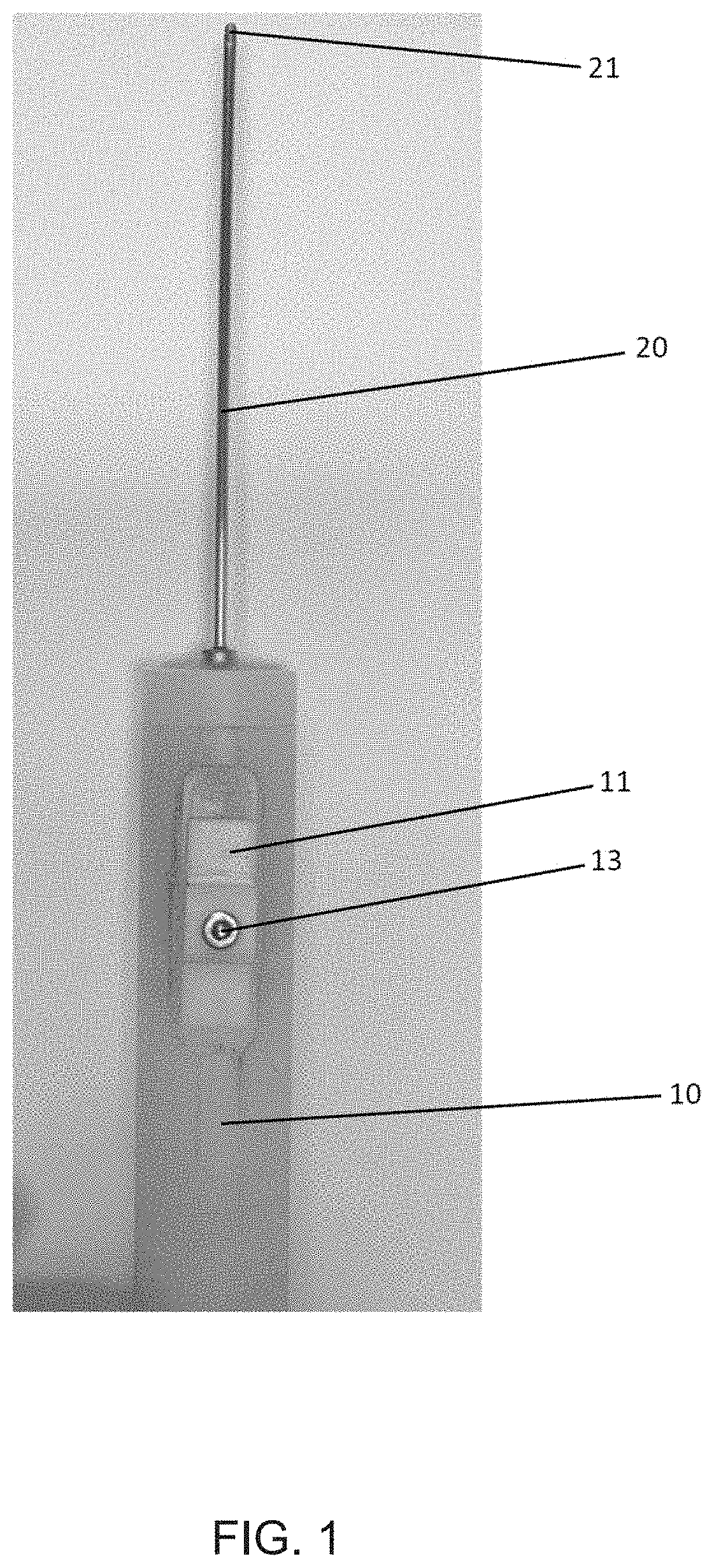
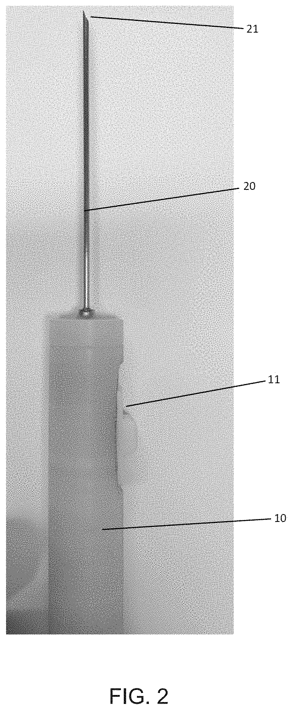
[0020]As can be seen in the embodiment of the invention shown in FIGS. 1 to 5, the meniscus suture device comprises a handle 10 for handling of the device by the surgeon having a push button 11 slidable in the axial direction of the handle 10.

[0021]The device further comprises a cannula 20 which extends from the handle and having a free extremity 21 opposite the handle. Inside the cannula 20 there is a movable rod 30 having a larger extension than the cannula 20. As can be seen in FIG. 5, in a first extremity, the movable rod 30 extends into the handle 10, having a driving mechanism 20 which connects to the push button 11 of the handle 10.

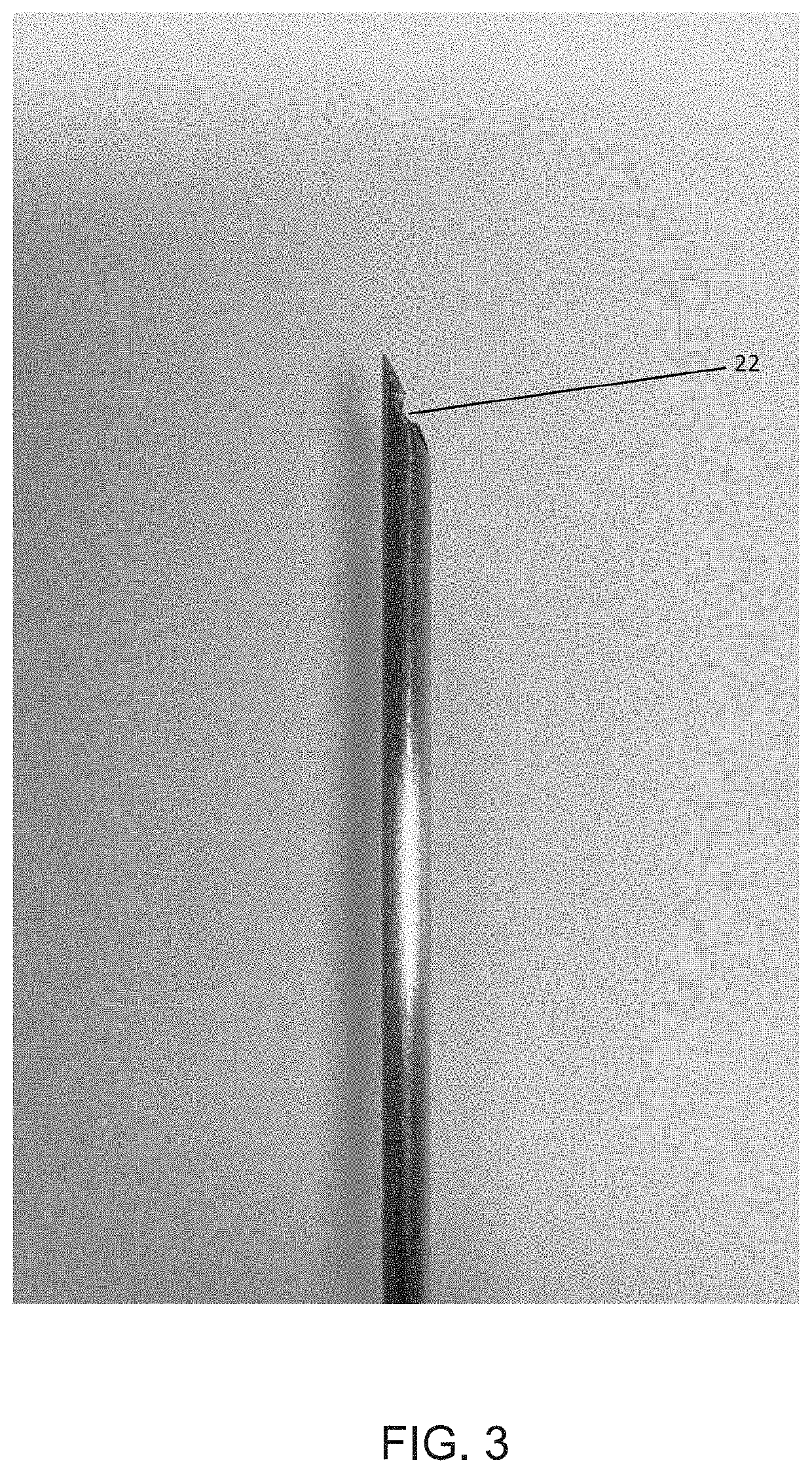
[0022]This connection between the driving mechanism 12 and the push button 11 allows that, by means of the button 11, the movable rod 30 is axially dislocated inside the cannula 20 until a second extremi...


PUM


Abstract

The present invention refers to a meniscus suture device comprising a handle for handling the device which comprises a push button with axial displacement, a cannula extending from the handle and having a free extremity opposite the handle, a movable rod housed and axially displaceable inside the cannula, the movable rod comprising a first extremity which extends inside the handle and a second extremity, opposite the handle, which has an indenture for capturing a suture thread, wherein the first extremity of the rod comprises a driving mechanism connected to the push button of the handle, for activating the axial displacement of the movable rod inside the cannula, and whereby when the axial displacement of the movable rod inside the cannula is activated, the second extremity of the rod extends outside the orifice of the cannula.

Description

[0001]The present invention refers to a meniscus suture device to assist in meniscus lesions repair surgeries, comprising a retractable hook in the extremity thereof to retain the suture, providing more ease to the operation.DESCRIPTION OF THE STATE OF THE ART[0002]Different devices used in surgical procedures for retaining the suture thread are already known to the state of the art.[0003]Document WO2015 / 089034 discloses a device to assist in holding a portion of a suture during an intra-abdominal suturing procedure, the device including an elongated tubular body, a handle, an inner member element, and a push button. The inner member element may include at least one grasping element that expands as the at least one grasping element is extended beyond a distal end of the elongated tubular. The device may include a proximal spring disposed within the push button and abutting against a proximal end of the inner member element to allow the at least one grasping element to retract into t...

Claims


Application Information

Patent Timeline
IPC IPC(8): A61B17/04A61B17/06
CPCA61B17/0483A61B17/06109A61B2017/06042A61B2017/00367A61B17/0469A61B2017/061A61B2017/06014
Inventor DE FARIA, JOSÉ LEONARDO ROCHAPEREIRA, CRISTIANO SIQUEIRA
Owner DE FARIA JOSÉ LEONARDO ROCHA
Why Eureka
Try Eureka