Motor

a motor and motor shaft technology, applied in the direction of magnetic circuit rotating parts, magnetic circuit shape/form/construction, transportation and packaging, etc., can solve the problems of many limitations in determining the number, size and the position and shape of grooves are affected, so as to reduce the magnetic flux, and reduce the cogging torque.

Pending Publication Date: 2022-09-08
LG INNOTEK CO LTD
View PDF0 Cites 0 Cited by
  • Summary
  • Abstract
  • Description
  • Claims
  • Application Information

AI Technical Summary

Benefits of technology

[0020]According to an embodiment, an advantageous effect of significantly reducing a cogging torque is provided by reducing magnetic fluxes at both end portions of a magnet. According to an embodiment, since a cogging torque waveform due to a p

Problems solved by technology

However, when the grooves are formed in the tooth of the stator, due to errors in positions of the teeth, there is a problem in that deviation in position and shape between grooves occur

Method used


Image

  • Motor
  • Motor
  • Motor

Examples


Embodiment Construction

[0034]Hereinafter, exemplary embodiments of the present invention will be described with reference to the accompanying drawings in detail. Purposes, specific advantages, and novel features of the invention will be made clear from the exemplary embodiments and the following detailed description in connection with the accompanying drawings. In addition, in the description of the present invention, detailed descriptions of related well-known functions, which unnecessarily obscure the gist of the invention, will be omitted.

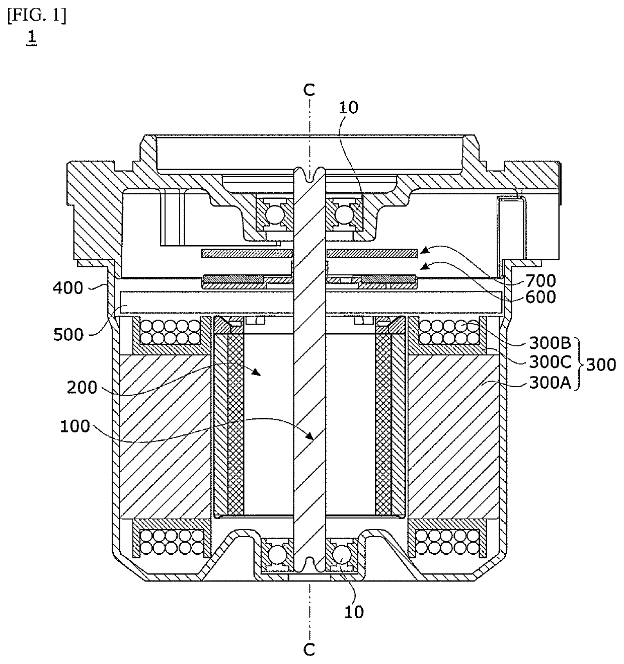
[0035]FIG. 1 is a view illustrating a motor according to an embodiment.

[0036]Referring to FIG. 1, a motor 1 according to the embodiment may include a shaft 100, a rotor 200, a stator 300, a housing 400, a busbar 500, a sensing unit 600, and a substrate 700. Hereinafter, the term “inside” is referred to as a direction from the housing 400 toward the shaft 100 which is a center of the motor, and the term “outside” is referred to as a direction opposite to “inside” which...


PUM


Abstract

The present invention may provide a motor including a rotor and a stator disposed to correspond to the rotor, wherein the rotor includes a rotor core and a magnet disposed on the rotor core, the rotor core includes a first region in which the magnet is disposed, the first region of the rotor core includes two grooves, one of the two grooves is disposed at a position corresponding to one end region of the magnet, and the other one of the two grooves is disposed at a position corresponding to the other end region of the magnet.

Description

TECHNICAL FIELD[0001]The present invention relates to a motor.BACKGROUND ART[0002]An electric power steering (EPS) system is an apparatus which secures turning stability of a vehicle and rapidly provides a restoring force so that a driver can safely drive the vehicle. The EPS system controls a vehicle's steering shaft to be driven by driving a motor using an electronic control unit (ECU) according to driving conditions detected by a vehicle speed sensor, a torque angle sensor, a torque sensor, and the like.[0003]The motor includes a stator and a rotor. The stator may include teeth constituting a plurality of slots, and the rotor may include a plurality of magnets facing the teeth. The adjacent teeth are disposed to be spaced apart from each other to constitute slot opens. In this case, a cogging torque may be generated due to a difference in magnetic permeability between the stator formed of a metal material and the slot open, which is an empty space, when the rotor rotates. The cog...

Claims


Application Information

Patent Timeline
IPC IPC(8): H02K1/276
CPCH02K1/276H02K2213/03H02K21/14H02K1/27B62D5/04B62D5/0403H02K1/2781H02K29/03
Inventor KIM, JAE YOUNG
Owner LG INNOTEK CO LTD
Why Eureka
Try Eureka