Permanent magnet-embedded motor and pump device

Pending Publication Date: 2022-08-04
MIKUNI CORP +1
View PDF4 Cites 0 Cited by
  • Summary
  • Abstract
  • Description
  • Claims
  • Application Information

AI Technical Summary

Problems solved by technology

In this permanent magnet-type motor, a cogging torque acting as a disturbance can be reduced by securing a skew in the permanent magnet, but since a plurality of permanent magnets is disposed in multiple stages in an axial direction of the rotating shaft, the structure is complicated, and this causes an increase in number of parts and an increase in costs

Method used


Image

  • Permanent magnet-embedded motor and pump device
  • Permanent magnet-embedded motor and pump device
  • Permanent magnet-embedded motor and pump device

Examples


Embodiment Construction

[0042]Hereinafter, embodiments of the disclosure will be described with reference to the accompanying drawings.

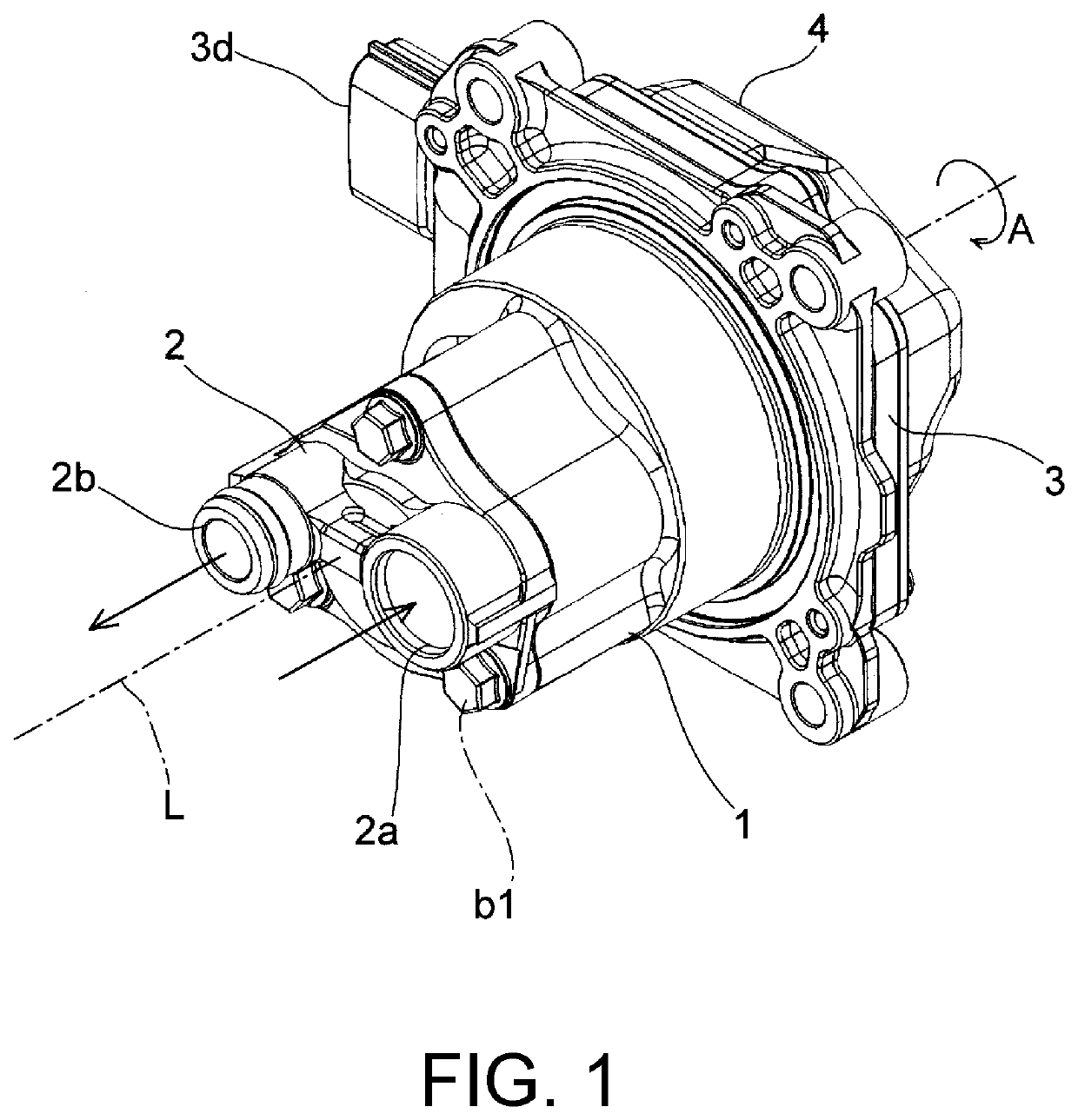
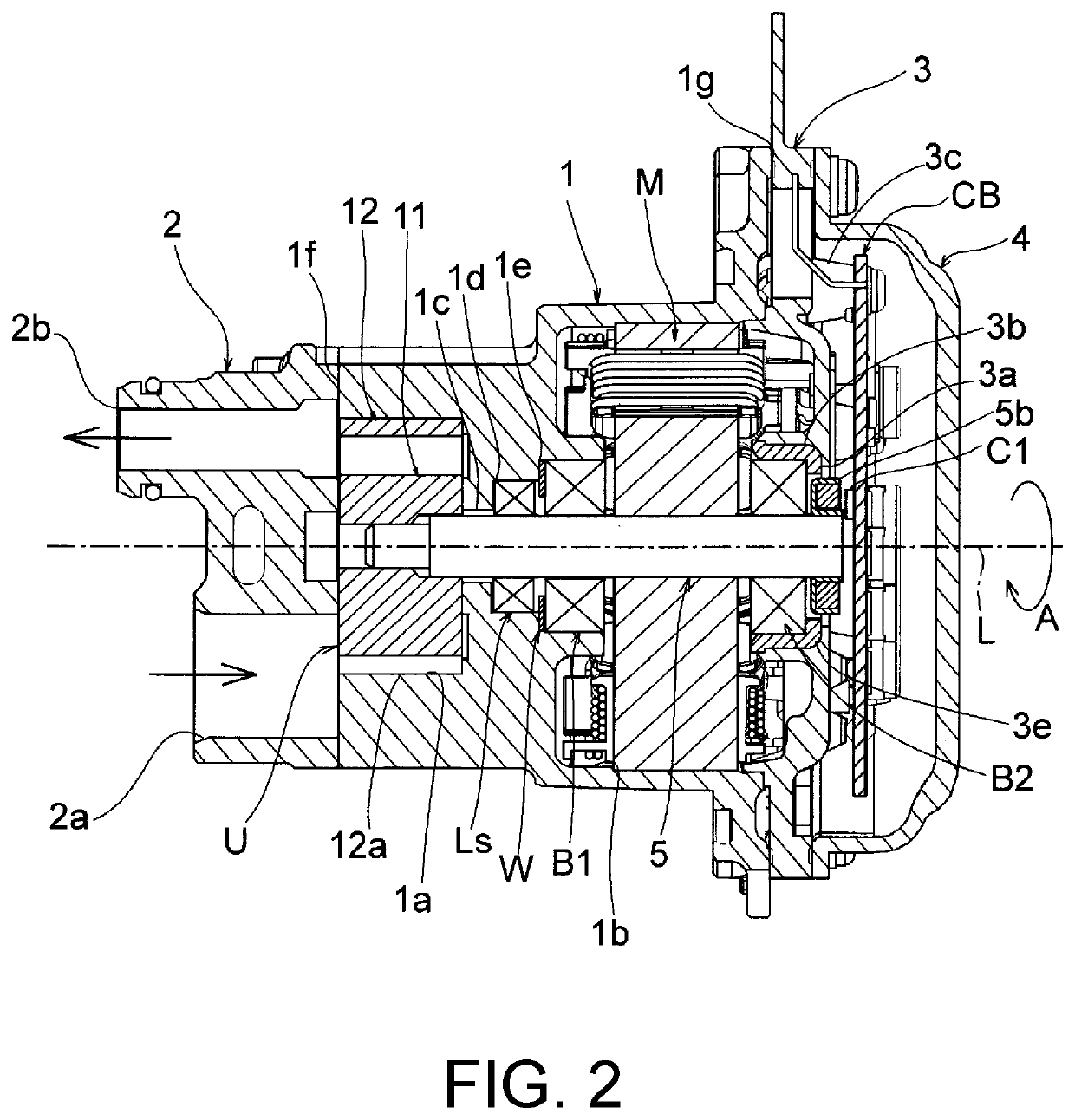
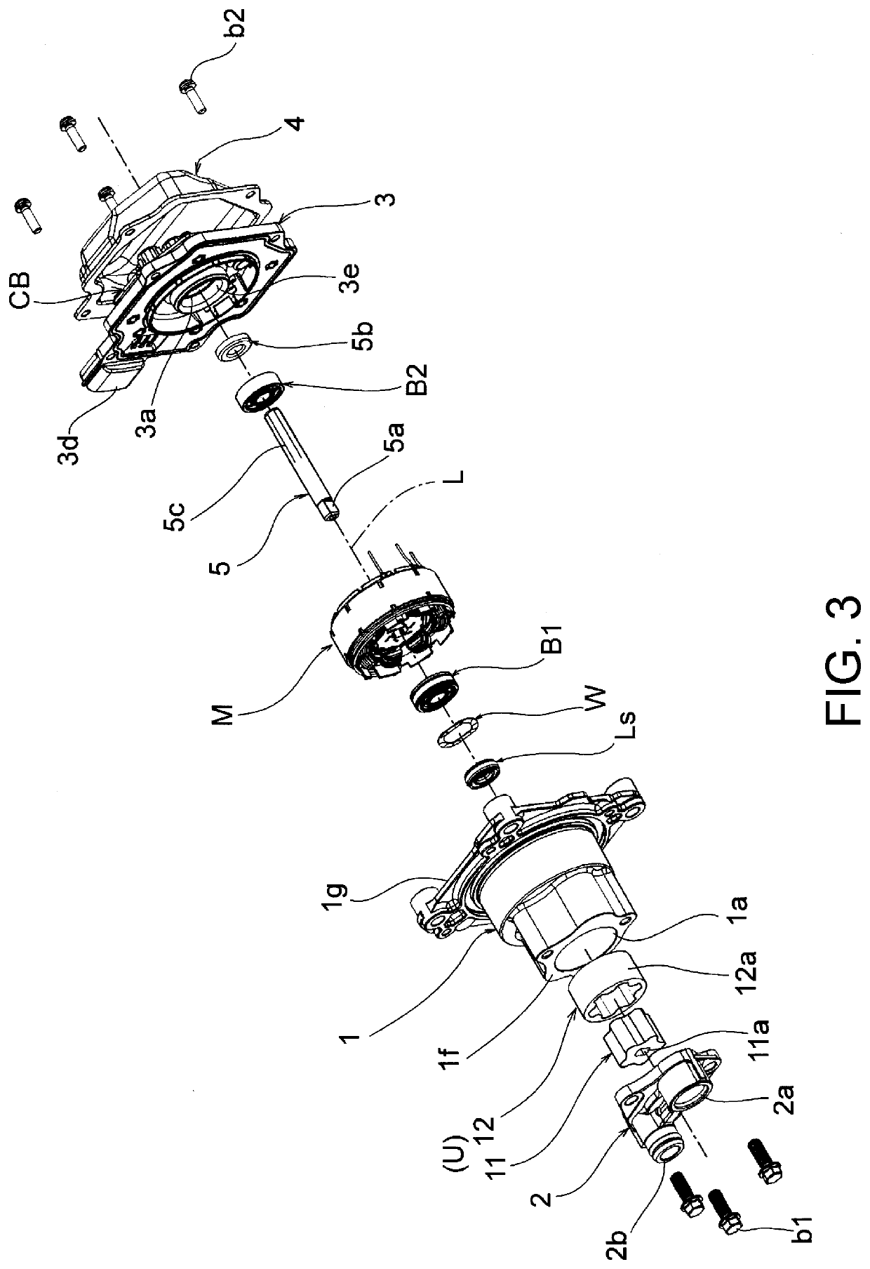
[0043]As illustrated in FIGS. 1 to 3, a pump device including a permanent magnet-embedded motor according to one embodiment includes a housing main body 1, a pump cover 2, a motor cover 3, a substrate cover 4, a rotating shaft 5, and a pump unit U, a permanent magnet-embedded motor M as a drive source, a circuit board CB, and the like.

[0044]The pump unit U suctions and discharges a fluid (here, oil), and is a trochoid pump including an inner rotor 11 and an outer rotor 12.

[0045]As illustrated in FIGS. 5 and 6, the permanent magnet-embedded motor M includes a stator St having a stator core 20, a bobbin 30, and a coil 40, and a rotor Rt having a rotor core 50 and a permanent magnet 60, and is a three-phase brushless motor having nine slots and six magnetic poles.

[0046]The housing main body 1 is formed of an aluminum material or the like, and as illustrated in FIGS. 2 and 3, i...


PUM


Abstract

A permanent magnet-embedded motor and a pump device are provided. The permanent magnet-embedded motor includes: a stator, including an annular stator core having teeth and slots disposed in a circumferential direction and coils wound around the teeth; and a rotor, including a rotor core having insertion fitting holes disposed to face the teeth of the stator and disposed in the circumferential direction and permanent magnets inserted and fitted into the insertion fitting holes. The rotor core includes: a groove-shaped recessed part, provided between the insertion fitting holes in the circumferential direction to define an outer circumferential magnetic pole part; a pair of notch parts, provided from both ends toward a center side of the outer circumferential magnetic pole part in the circumferential direction to be recessed inward with respect to an outer circumferential contour; and an outer circumferential magnetic pole surface, sandwiched between the pair of notch parts.

Description

CROSS-REFERENCE TO RELATED APPLICATIONS[0001]This application claims the priority benefit of Japan Application No. 2021-012789, filed on Jan. 29, 2021. The entirety of the above-mentioned patent application is hereby incorporated by reference herein and made a part of this specification.BACKGROUNDTechnical Field[0002]The disclosure relates to a permanent magnet-embedded motor including a stator in which a coil is wound and a rotor in which a permanent magnet is embedded, and a pump device using the same as a drive source.Description of Related Art[0003]As a conventional permanent magnet-embedded motor, a permanent magnet-type motor including an annular stator having teeth and slots disposed in a circumferential direction, coils wound around the teeth, and a rotor that is rotatably disposed inside the stator and in which a skew is given to embedding holes disposed in the circumferential direction to embed permanent magnets therein, in which the permanent magnets are embedded in multi...

Claims


Application Information

Patent Timeline
IPC IPC(8): H02K7/14H02K1/276F04C11/00F04C23/02
CPCH02K7/14H02K1/276F04C2240/40F04C23/02F04C11/008H02K1/24H02K1/146H02K21/16F04C2/10H02K2213/03H02K2201/03H02K29/03
Inventor SUZUKI, SHINISHIKAWA, TAKEOTAKATA, KOTA
Owner MIKUNI CORP
Why Eureka
Try Eureka