Motor

a motor and motor technology, applied in the direction of dynamo-electric machines, magnetic circuit rotating parts, magnetic circuit shape/form/construction, etc., can solve the problems of large difference in the rate of change of magnetoresistance, vibration and noise, and mechanical and electrical noises,

Active Publication Date: 2022-07-05
HANON SYST
View PDF14 Cites 0 Cited by
  • Summary
  • Abstract
  • Description
  • Claims
  • Application Information

AI Technical Summary

Benefits of technology

[0029]In a motor according to the present invention, there is an effect of significantly reducing a cogging torque and significantly reducing a noise and vibrations of the motor by minimizing a change in a magnetoresistance according to rotation of a rotor. More specifically, in a brushless motor according to the present invention, a central portion of an inner peripheral surface of a permanent magnet is formed in a cylindrical shape and both end portions of the inner peripheral surface of the permanent magnet are formed in a chamfered shape, such that when a rotor rotates from an end of one pole of the permanent magnet to the next pole, a change in a magnetoresistance is gradually reduced and is then gradually increased again. Therefore, an effect of significantly reducing a cogging torque may be obtained. In addition, in the brushless motor according to the present invention, both distal ends of an outer peripheral surface of a stator pole shoe have a chamfered shape to increase the effect as described above, such that an effect of further reducing the cogging torque may be obtained.
[0030]Furthermore, in the brushless motor according to the present invention, the stator pole shoe formed of an electrical sheet to have a density higher than that of the permanent magnet is formed in the chamfered shape, such that an effect of more effectively reducing a weight of a component formed of a material having a high density and significantly reducing a weight of the motor itself ultimately may be obtained.

Problems solved by technology

Among the DC motors, a motor to which a brush is attached serves to allow a current to flow to a coil and commutate the current by a contact between a commutator and the brush, but has a disadvantage that mechanical and electrical noises are generated and the brush is worn.
As a result, vibrations and a noise are caused in a cooling fan or the like, which is a motor driving system.
However, even in a case where the notches 124 are formed, there is still a large difference in a rate of change in the magnetoresistance depending on a rotation angle, and thus, there is a problem in that the noise and the vibrations are not greatly reduced.
However, even with Related Art Document 1, there is a limitation that it is difficult to obtain performance of improving the cogging torque and the torque ripple as much as sufficiently necessary and a reduction in the weight of the motor is not considered at all.

Method used


Image

  • Motor
  • Motor
  • Motor

Examples


Embodiment Construction

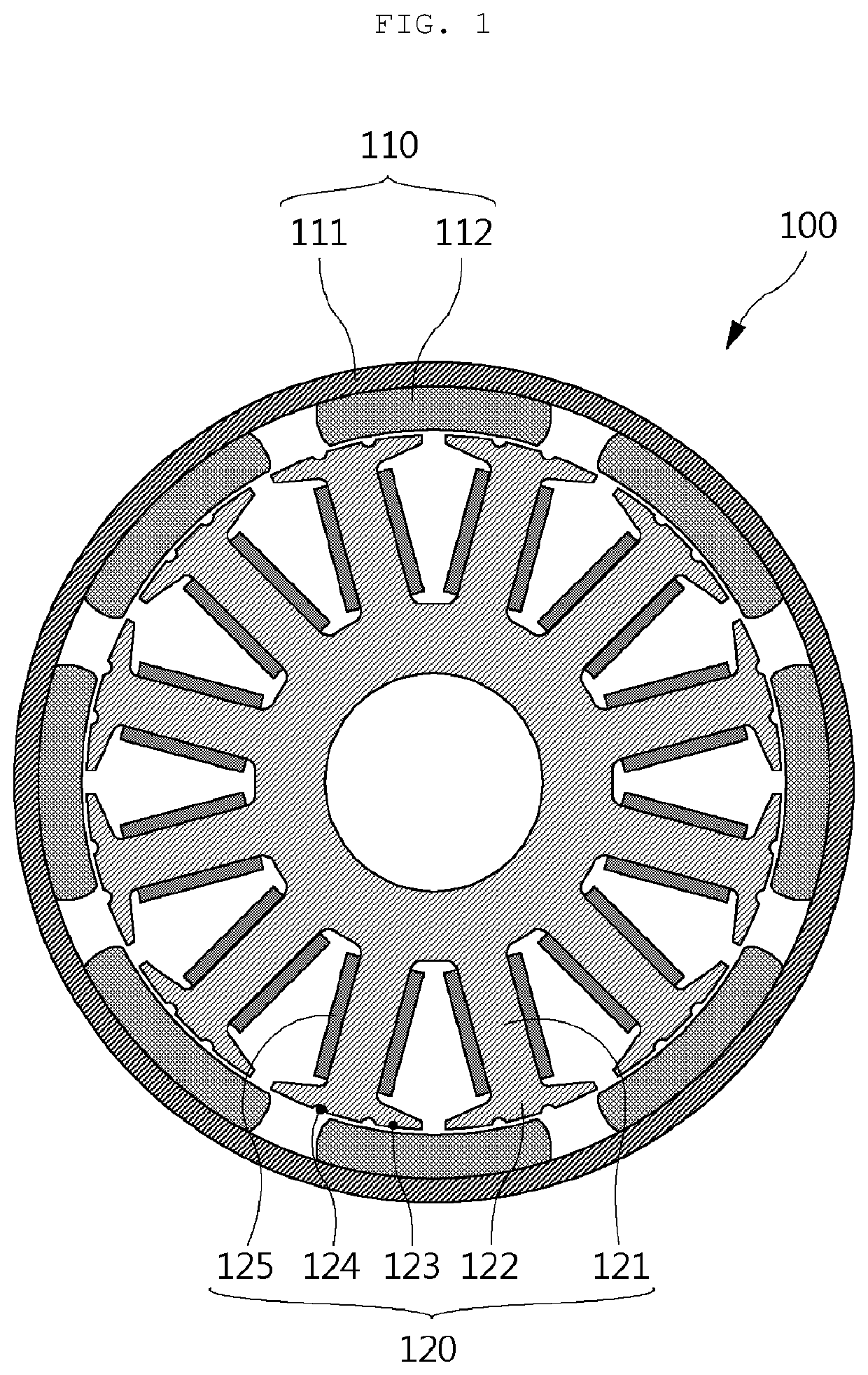
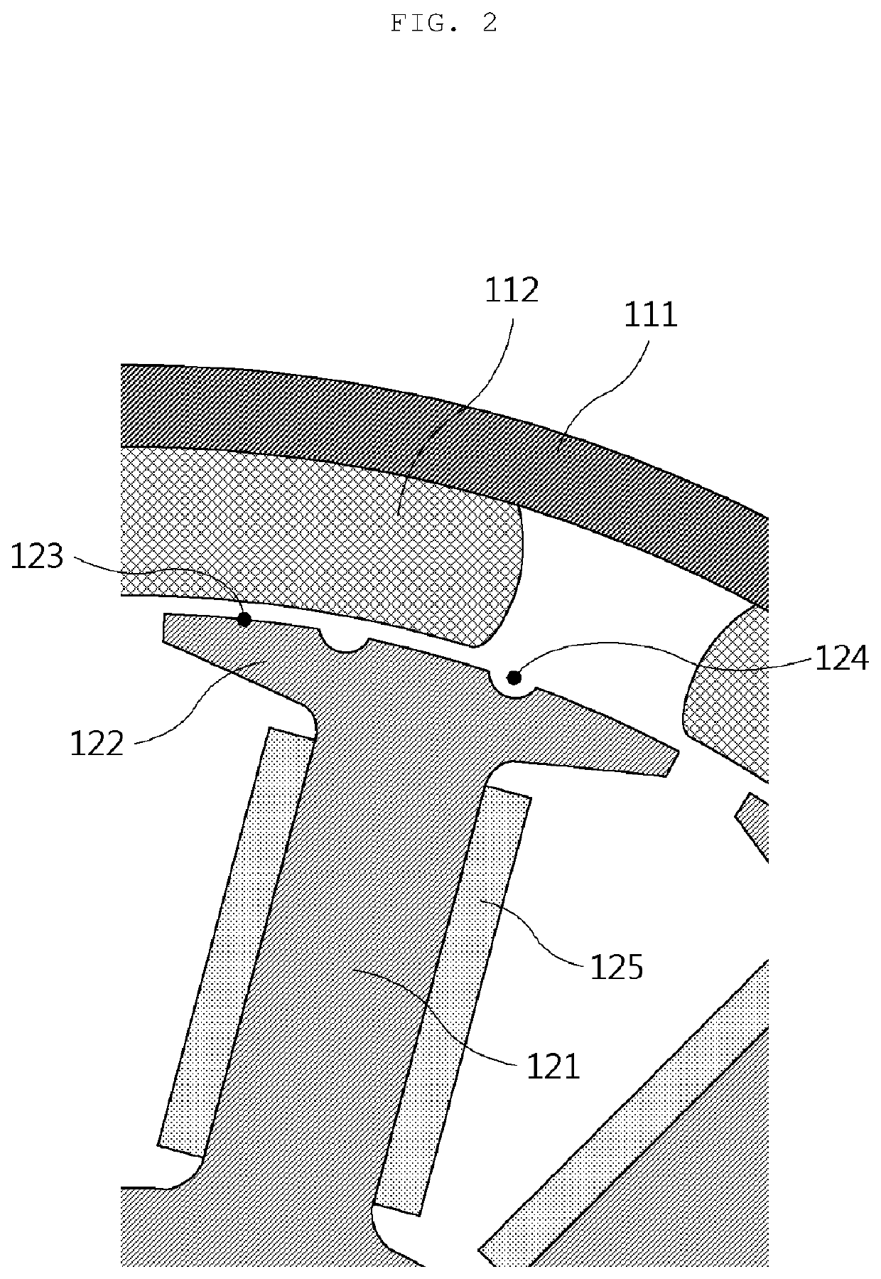
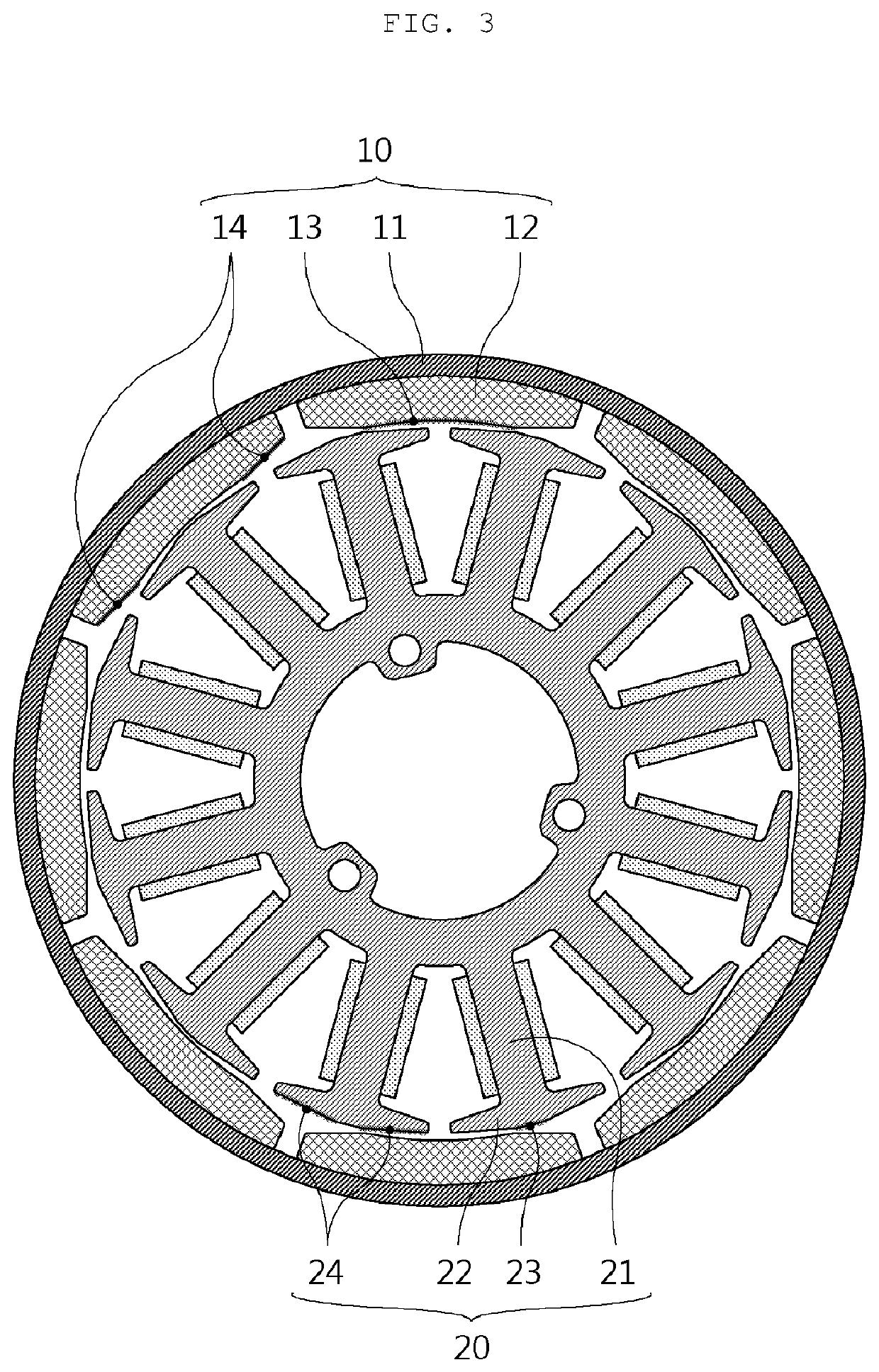
[0040]10, 110: rotor[0041]11, 111: rotor core[0042]12, 112: permanent magnet[0043]13: inner peripheral surface of central portion of permanent magnet[0044]14: inner peripheral surfaces of both end portions of permanent magnet[0045]20, 120: stator[0046]21, 121: stator teeth[0047]22, 122: pole shoe[0048]23: outer peripheral surface of central portion of pole shoe[0049]24: outer peripheral surfaces of both end portions of pole shoe[0050]25, 125: coil[0051]C: center of rotation of rotor[0052]CL: center line of permanent magnet

Best Mode

[0053]FIG. 3 is a cross-sectional view illustrating a brushless motor according to an exemplary embodiment of the present invention. First, a basic structure of the brushless motor will be described with reference to FIG. 3.

[0054]As illustrated in FIG. 3, the brushless motor 100 according to the present invention is configured to include a rotor 10 including a rotor core 11 and a plurality of permanent magnets 112 disposed on an inner peripheral surface of...


PUM


Abstract

The present invention relates to a brushless motor, and an objective of the present invention is to provide a brushless motor which can significantly reduce the cogging torque and torque ripple of the motor by minimizing the rate of change of magnetoresistance in accordance with a change in position of a rotor through the optimization of the shape design of the rotor and a stator, and can also reduce the weight of the brushless motor through the optimization of the shape design taking into consideration the materials of the rotor and the stator.

Description

[0001]This application is a national phase under 35 U.S.C. § 371 of International Application No. PCT / KR2018 / 006465 filed Jun. 7, 2018, which claims priority from Korean Patent Application Nos. 10-2017-0072617 filed Jun. 9, 2017 and 10-2018-0064748 filed Jun. 5, 2018. The entire contents of these applications are incorporated herein by reference in their entirety.TECHNICAL FIELD[0002]The present invention relates to a motor, and more particularly, to a motor in which a rotor rotates outside a stator and a permanent magnet is provided in the rotor.BACKGROUND ART[0003]In general, a motor is a device converting electrical energy into mechanical energy in a magnetic field in which a current flows, and may be classified according to various references such as a type of power supply, positions of a rotor and a stator, and whether or not to use a permanent magnet.[0004]For example, the motor is divided into a direct current (DC) motor and an alternating current (AC) motor according to the ...

Claims


Application Information

Patent Timeline
Patent Type & Authority Patents(United States)
IPC IPC(8): H02K1/27H02K29/03H02K1/2786H02K21/22
CPCH02K29/03H02K1/2786H02K21/22H02K2213/03H02K2201/03H02K1/2791H02K1/27915H02K1/146
Inventor SHIN, HYEON JAECHO, SEONG KOOKKIM, HO YOUNLEE, JAE WONIM, HO BINJUNG, KYUNG HUN
Owner HANON SYST
Why Eureka
Try Eureka