Fan device, fan-equipped garment, and recording medium
a technology of fan device and fan garment, which is applied in the direction of protective garment, pump control, non-positive displacement fluid engine, etc., can solve the problem of not being able to maintain a drive mode with a large air volume for a long time, and achieve the effect of reducing the number of fans and reducing the number of nois
- Summary
- Abstract
- Description
- Claims
- Application Information
AI Technical Summary
Benefits of technology
Problems solved by technology
Method used
Image
Examples
second embodiment
[0170]The fan device 2A of the second embodiment will be explained based on FIG. 7. The same signs are given to the same components as those of the fan device 2 of the first embodiment. Explanation is omitted.
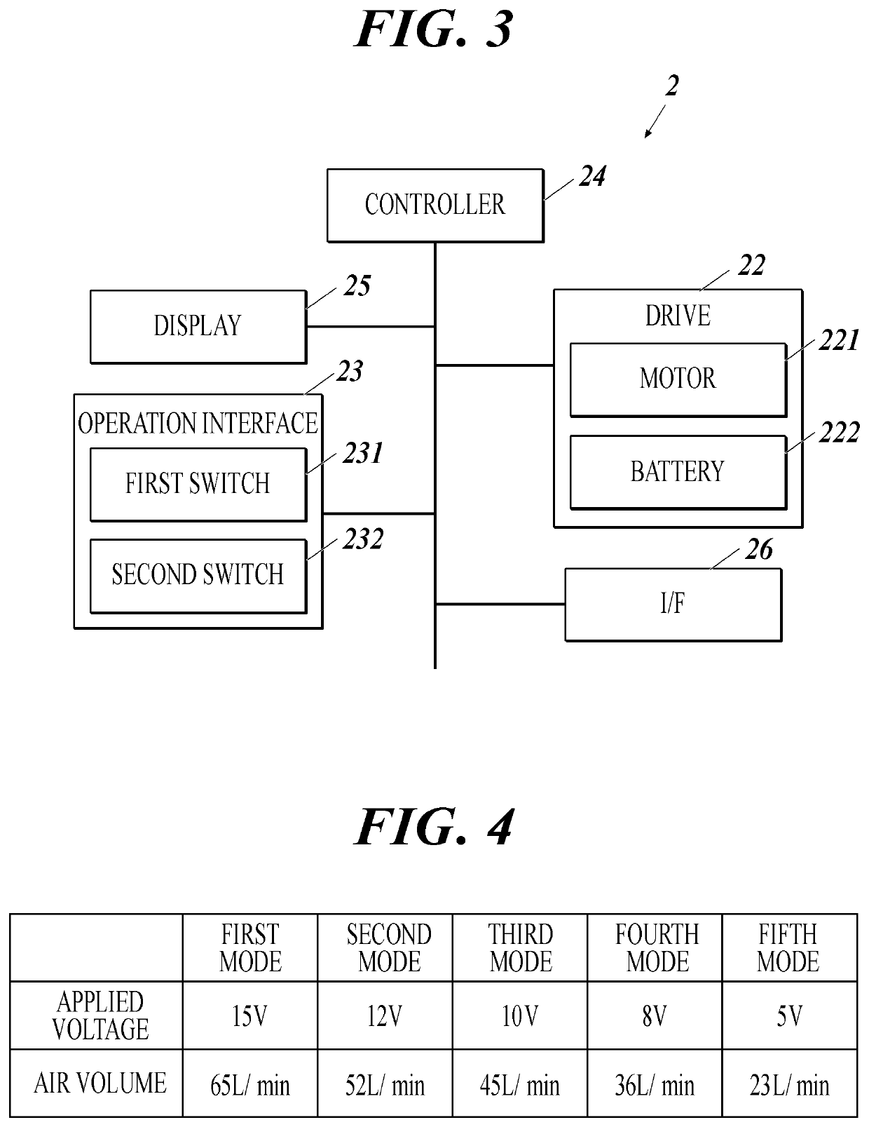
[0171]In addition to the first to fifth modes shown in the first embodiment, the fan device 2A of the second embodiment has a fluctuation mode that alternates between the third and fourth modes. It comes to a total of six modes.
[0172]In the fluctuation mode, the drive 22 can operate in the third or fourth mode for a time of any length, and switching between the third and fourth modes can be done in a time of any length. For example, the drive time in the fourth mode with a small air volume may be longer than the drive time in the third mode with a large air volume. In this way, even when the fan device 2A is driven in the fourth mode, a user feels that the same amount of air is being blown as in the third mode.
Flow of Switching of Drive Status when First Switch is Pressed
[0173]...
third embodiment
[0183]The fan device 2B of the third embodiment will be described based on FIGS. 8 and 9. The same signs are given to the same components as those of the fan device 2 of the first embodiment. Explanation is omitted.
[0184]As shown in FIG. 8, the fan device 2B of the third embodiment has a single switch 231B as the operation interface 23B.
Switch
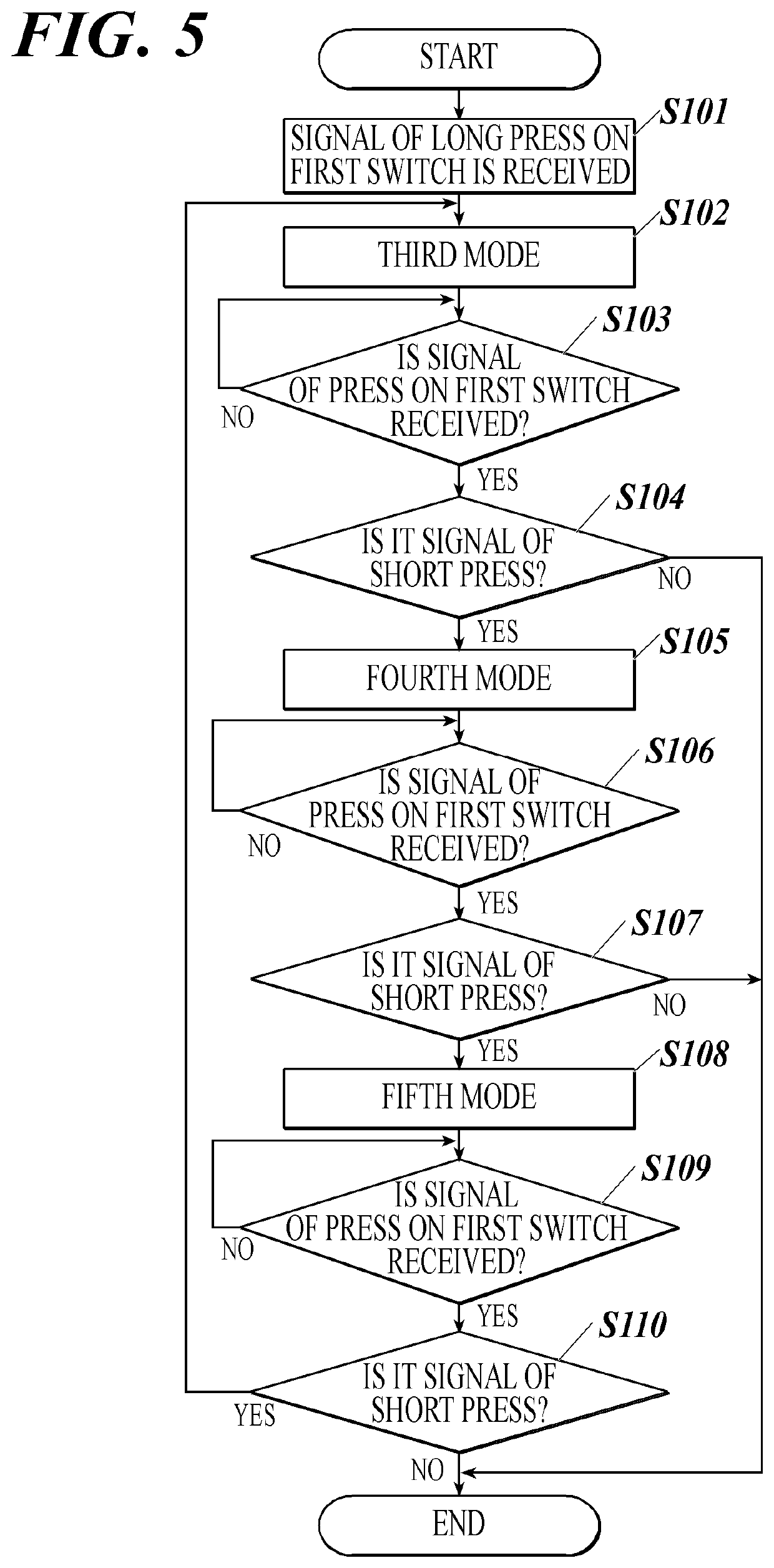
[0185]Long press on the switch 231B turns on / off the drive 22. Short press on the switch 231B switches the mode of the drive 22. When the drive 22 is turned on, the controller 24B makes the drive 22 operate in the third mode. Every time the short press is performed on the switch 231B, the controller 24B cyclically switches the mode to the fourth mode, the fifth mode, the third mode, and so on.
Flow of Switching of Drive Status when Switch is Pressed
[0186]FIG. 9 is a flowchart explaining switching of modes in the fan device 2B of the third embodiment.
[0187]In the following explanation, explanations that overlap with explanations of Step S101 to S...
fourth embodiment
[0201]The fan device 2C of the fourth embodiment will be explained based on FIG. 10.
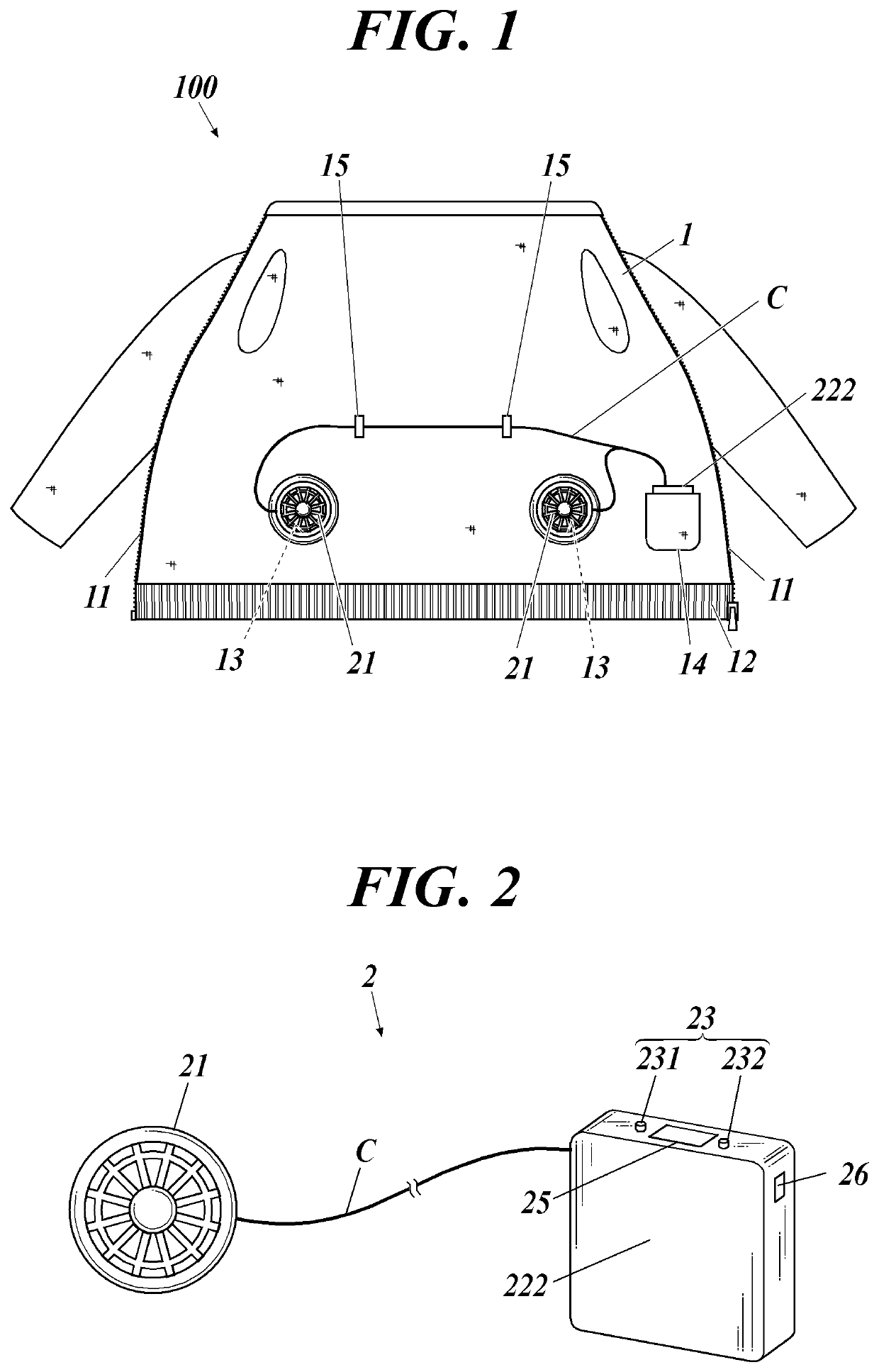
[0202]The fan device 2C of the fourth embodiment shows an example in which the configuration of the fan devices 2 to 2B of the first to third embodiments is specifically configured by:
[0203]a fan unit 28 including a fan 21 and a motor 221 for driving the fan 21;
[0204]a power source 27 for driving the fan 21; and
[0205]a connection (cable) 4 that connects the power source 27 with the fan unit 28.
[0206]In the following, the components with the same signs and names as those of the fan device 2 of the first embodiment have the same functions and effects.
[0207]The fan 21 includes, for example, a propeller housed in a case. The fan 21 is detachably mounted in the fan mount hole 13. The fan 21 includes a transmission mechanism (not shown) that transmits the rotational force of the motor 221 to the propeller.
[0208]The power source 27 includes:
[0209]a battery 222 which applies a voltage necessary to drive the ...
PUM
 Abstract
Description
Claims
Application Information
 - R&D
- Intellectual Property
- Life Sciences
- Materials
- Tech Scout
- Unparalleled Data Quality
- Higher Quality Content
- 60% Fewer Hallucinations
Browse by: Latest US Patents, China's latest patents, Technical Efficacy Thesaurus, Application Domain, Technology Topic, Popular Technical Reports.
© 2025 PatSnap. All rights reserved.Legal|Privacy policy|Modern Slavery Act Transparency Statement|Sitemap|About US| Contact US: help@patsnap.com


