Eureka AIR delivers breakthrough ideas for toughest innovation challenges, trusted by R&D personnel around the world.

Liquid Discharging Head

Pending Publication Date: 2022-09-22
BROTHER KOGYO KK
View PDF0 Cites 0 Cited by
  • Summary
  • Abstract
  • Description
  • Claims
  • Application Information

AI Technical Summary

Benefits of technology

The patent is about a liquid discharging head that has a bent flow direction, which increases the flow rate at the end of the nozzle. This allows the head to effectively remove any thickened ink that may accumulate at the end of the nozzle. The technical effect of this design is to improve the efficiency and reliability of liquid discharging heads.

Problems solved by technology

Therefore, it is not possible to remove adequately the thickened ink at the end portion of the nozzle.

Method used


Image

  • Liquid Discharging Head
  • Liquid Discharging Head
  • Liquid Discharging Head

Examples


Embodiment Construction

[0031]An embodiment of the present disclosure will be described below.

[0032]

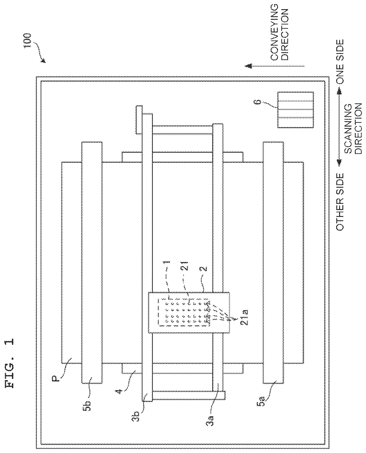
[0033]As depicted in FIG. 1, a printer 100 according to the present embodiment includes an ink-jet head 1 (“liquid discharging head” of the present disclosure), a carriage 2, guide rails 3a and 3b, a platen 4, conveying rollers 5a and 5b, and an ink tank 6.

[0034]The carriage 2 is supported by the two guide rails 3a and 3b extended in a scanning direction (leftward-rightward direction of FIG. 1) along a horizontal direction, and moves in the scanning direction along the guide rails 3a and 3b. The ink-jet head 1 is mounted (installed) on the carriage 2, and moves in the scanning direction together with the carriage 2. In the description below, a rightward side in FIG. 1 of the scanning direction is let to be “one side” and a leftward side in FIG. 1 is let to be “the other side”.

[0035]Inks of four colors, black, yellow, cyan, and magenta are supplied to the ink-jet head 1 from the ink tank 6 via tubes not depic...


PUM


Abstract

A liquid discharging head includes: individual channels; a first common liquid chamber provided commonly for the individual channels; and a second common liquid chamber provided commonly for the individual channels. Liquid is supplied from the first common liquid chamber to the individual channels and the liquid flows into the second common liquid chamber from the individual channels. Each of the individual channels has: a pressure chamber; a first channel; a nozzle connected to the first channel and configured to discharge the liquid; a second channel separated from the nozzle in a first direction and connecting the pressure chamber and the first channel; and a third channel connected to the first channel on a side opposite to the second channel in the first direction with the nozzle sandwiched between the third channel and the second channel.

Description

CROSS REFERENCE TO RELATED APPLICATIONS[0001]The present application claims priority from Japanese Patent Application No. 2021-047004, filed on Mar. 22, 2021, the disclosure of which is incorporated herein by reference in its entirety.BACKGROUND[0002]The present disclosure relates to a liquid discharging head which discharges liquid from nozzles.Description of the Related Art[0003]As an example of a liquid discharging head which discharges liquid from nozzles, an ink-jet recording head which discharges ink from nozzles has been known. The ink-jet recording head includes a plurality of individual channels communicating with a plurality of nozzles respectively, and a first common liquid chamber provided commonly for the plurality of individual channels to supply ink to the plurality of individual channels. The plurality of individual channels has a plurality of pressure chambers. Moreover, by changing pressure on the ink in the plurality of pressure chambers by a piezoelectric actuato...

Claims


Application Information

Patent Timeline
IPC IPC(8): B41J2/14
CPCB41J2/14B41J2002/14419B41J2202/11B41J2202/12B41J2002/14459B41J2002/14306B41J2/14233
Inventor KANZAKI, SHOTAROSUGIURA, KEITA
Owner BROTHER KOGYO KK
Why Eureka
Eureka Blog
Learn More