
Frac manifold isolation tool

a technology of manifold and manifold, which is applied in the direction of fluid removal, wellbore/well accessories, sealing/packing, etc., can solve the problems of increasing the cost of using a zipper manifold, the cost of valves that have traditionally been used to control the flow of fracturing fluid to individual trees, and the cost of valves can easily be several hundred thousand dollars. , to achieve the effect of less expensiv

Pending Publication Date: 2022-09-29
OIL STATES ENERGY SERVICES
View PDF0 Cites 0 Cited by
  • Summary
  • Abstract
  • Description
  • Claims
  • Application Information

AI Technical Summary

Benefits of technology

The frac manifold isolation tool uses a mandrel to control the flow of frac fluid to a wellhead or frac tree. This tool can replace or reduce the number of valves that would otherwise control fluid in the manifold, making the use of a frac manifold less expensive and more efficient. The technical effect of this tool is improved control over frac fluid flow without the need for a valve cabinet, reducing costs and making the process more efficient.

Problems solved by technology

In particular, the valves that have traditionally been used to control the flow of fracturing fluid to individual trees are expensive and greatly increase the cost of using a zipper manifold.
With multiple valves required for each frac tree, when a zipper manifold is arranged to connect to several adjacent wells, the cost of the valves can easily be several hundred thousand dollars.

Method used


Image

  • Frac manifold isolation tool
  • Frac manifold isolation tool
  • Frac manifold isolation tool

Examples


Embodiment Construction

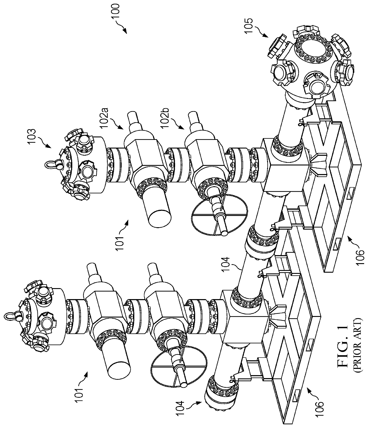
[0035]FIG. 1 illustrates an example of a prior art zipper manifold 100. The manifold may be positioned vertically, as shown in FIG. 1, or it may be positioned horizontally. The frac manifold 100 can include two or more well configuration units 101. Each well configuration unit 101 includes one or more valves 102 and a bridge connector header 103, and the well configuration units 101 may be collectively or individually (as shown) positioned on skids 106. Each bridge connector header 103 connects to a frac tree. As shown in FIG. 1, each well configuration unit 101 typically includes a hydraulically actuated valve 102a and a manually actuated valve 102b. The well configuration units 101 of the zipper manifold 100 are connected together by zipper spools 104, and the final zipper spool 104 may be capped off or connected to other well configurations 101 as needed. The zipper manifold 100 connects to the output of the frac pump at the frac supply header 105.

[0036]The bridge connector head ...


PUM


Abstract

A frac manifold isolation tool configured to connect to a zipper spool, and comprising a mandrel that is axially movable and a hydraulic setting tool configured to move the mandrel from an open position, in which fracturing fluid is allowed to flow from a zipper spool to a connected frac tree, to a closed position, in which the mandrel and its associated cup tool direct flow.

Description

TECHNICAL FIELD[0001]The present disclosure relates generally to oil or gas wellbore equipment, and, more particularly, to a frac manifold.BACKGROUND[0002]Frac manifolds, also referred to herein as zipper manifolds, are designed to allow hydraulic fracturing operations on multiple wells using a single frac pump output source. Frac manifolds are positioned between the frac pump output and frac trees of individual wells. A frac manifold system receives fracturing fluid from the pump output and directs it to one of many frac trees. Fracturing fluid flow is controlled by operating valves to isolate output to a single tree for fracking operations.[0003]Frac zipper manifolds may be rigged up to frac trees before frac equipment arrives at the well site. Once onsite, the frac equipment need only be connected to the input of the frac manifold. Because individual frac trees do not need to be rigged up and down for each fracking stage and because the same frac equipment can be used for frackin...

Claims


Application Information

Patent Timeline
Patent Type & Authority Applications(United States)
IPC IPC(8): E21B43/26
CPCE21B43/2607E21B33/03
Inventor LIVINGSTON, JIMMYZHAO, HAIFANGMCGUIRE, BOBCLAXTON, MICKEYARTHERHOLT, DANNYGRASSMANN, DARIN
Owner OIL STATES ENERGY SERVICES
Features
  • Generate Ideas
  • Intellectual Property
  • Life Sciences
  • Materials
  • Tech Scout
  • Unparalleled Data Quality
  • Higher Quality Content
  • 60% Fewer Hallucinations
Learn More