
Non-penetrating roof safety systems and methods of installation and use for sloped rooftops

a safety system and roof technology, applied in the direction of safety belts, construction, building materials handling, etc., can solve the problems of limiting the user's ability to access all areas of the roof surface, the repair of the hole, and the failure point of water intrusion into the roo

Pending Publication Date: 2022-10-06
BALLANTYNE GEAR INC
View PDF0 Cites 0 Cited by
  • Summary
  • Abstract
  • Description
  • Claims
  • Application Information

AI Technical Summary

Benefits of technology

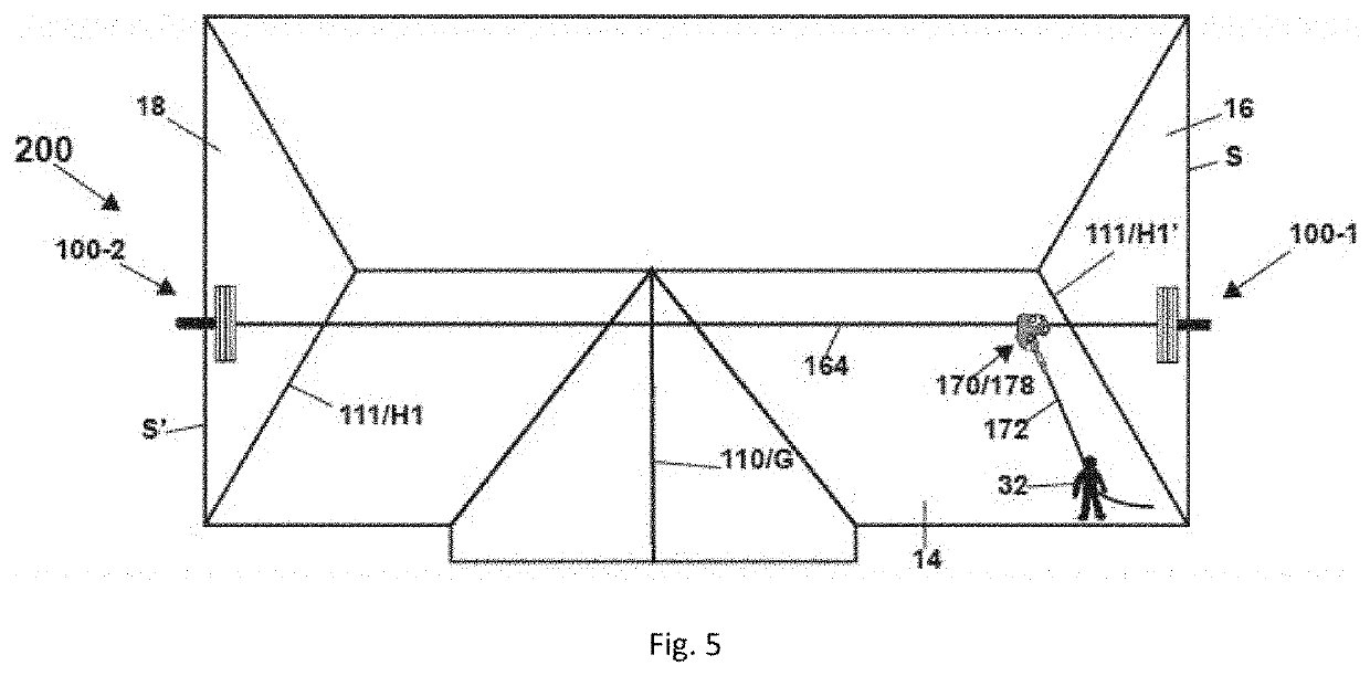
The invention is a roof safety system that allows access to multiple areas of a roof without needing to permanently attach components to the roof or building. The system includes roof anchors, an anchor line, and a repositionable sliding anchor that connects to a lifeline. This allows users to easily access the roof for tasks like repair or installation, and can be installed by a single user if additional assistance is not available. The system also allows multiple users to access the roof simultaneously and use the same anchor line while being protected from falls.

Problems solved by technology

Many prior art roof safety systems require some penetration of the roof's surface for installation, such as through a screw or bolt inserted into the roof's surface or substructure, which creates a failure point for water intrusion into the roof or requires repair of the hole when the safety system is removed.
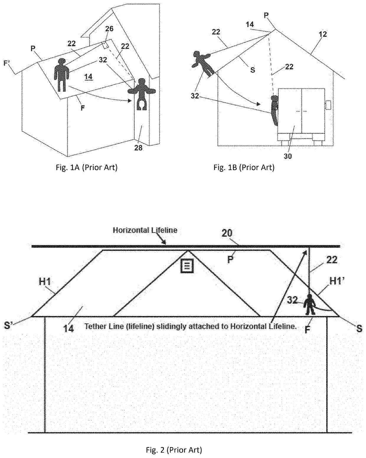
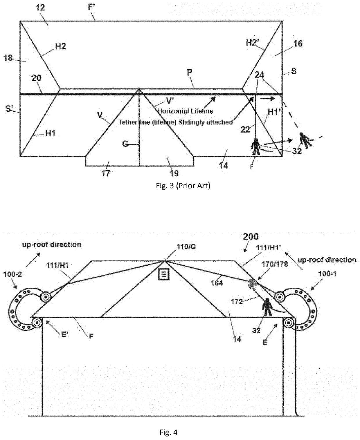
Many prior art roof safety systems also either have a fixed anchorage point on the roof, a tether line across the roof (such as a horizontal lifeline) that does not allow a user to anchor to a particular position on the tether line, and / or involve the use of a fixed length lifeline (or lanyard) connecting the user to the fixed anchorage point or horizontal lifeline.
These systems limit a user's ability to access all areas of the roof's surface and do not provide adequate protection against falls, particularly swing falls, as further discussed below.
A great shortcoming of the '030 system is that a user installing the system is required to carry the hook members and the weight onto the roof for installation, with no protection from falls during the installation process.
It is dangerous to walk on a roof without fall protection, but when a user is carrying his / her gear, including the large sized hook members, a weight or weights, the tether lines, and other gear, it becomes much more dangerous.
If any protection is desired during installation of the '030 safety system, it must be from a separate safety system, making it more complex, more expensive, and installing the separate system will likely add risks of injury to the user.
For example, the user, standing precariously on a steep roof with no fall protection, rolling the anchoring device down the roof, might allow the tether line to slip from his / her fingers so that the hook member rolls off the roof, potentially injuring another worker or other person or property that is below, and likely damaging the hook member (which is an expensive piece of gear) so that it is now unusable.
Additionally, the user may experience a loss of balance after losing his / her grip on the tether line, further increasing the risk of a fall.
Additionally, once installed, the '030 system only allows attachment of a lifeline at the connection of the two tether lines from the opposing hook members, resulting in a swing fall hazard at almost all positions at the roof edge and many areas that are not at the roof edge, resulting in limited access to the roof where the user is properly protected from falls.

Method used


Image

  • Non-penetrating roof safety systems and methods of installation and use for sloped rooftops
  • Non-penetrating roof safety systems and methods of installation and use for sloped rooftops
  • Non-penetrating roof safety systems and methods of installation and use for sloped rooftops

Examples


Embodiment Construction

[0082]As used herein, portions of a roof structure are designated by certain letters, such as V for a valley, G for a gable ridge, H for a hip, P for a primary ridge, F for a front / rear edge, S for a side edge, and E for an eave. Any such letter including a prime indicator (e.g., left side edge S′ or rear edge F′) is intended to indicate a roof portion that is substantially opposite a similar roof portion without the prime indicator (e.g., right side edge S or front roof edge F). The description of various preferred embodiments of the invention in relation to such portions of the roof structure are not intended to be limiting. For example, a roof anchor 100-1 is primarily described herein as being installed on a right side edge S, but can also be installed on left side edge S′, front edge F, or rear edge F′. The references to the portions of the roof structure are only for ease of understanding the various preferred embodiments of roof safety systems according to the invention and h...


PUM


Abstract

An improved roof safety system allows temporary installation without damaging the roof or building by using non-penetrating C-shaped anchors to hook onto eaves on opposing sides of the roof with the anchors connected by a single, continuous anchor line under tension. Installation of primary components do not require a user to access the roof, as they may be installed from the ground or a ladder position. Slidable anchors connectable to an anchor line and lifeline allow free movement along the line in a first direction and block movement in a second opposite direction, allowing a user to anchor to the line at a selected position and then securely move about the roof's surface in an area generally disposed in the second direction while being protected from a fall. An optional wedge-stopper can aid in single-user installation.

Description

CROSS-REFERENCE TO RELATED APPLICATIONS[0001]This patent application is a continuation-in-part of U.S. patent application Ser. No. 16 / 876,674 filed on May 18, 2020, which is a continuation-in-part of U.S. patent application Ser. No. 15 / 906,113 filed on Feb. 27, 2018, the disclosures of which are incorporated by reference herein.RELATED ART[0002]Different types and configurations of roof safety systems that provide an anchorage point or an anchorage line to provide fall restraint, fall arrest, and rope access for use in construction, repair, inspection, or other tasks on a roof's surface are well known in the prior art. Such systems are configured to prevent injury or death by restraining a user from falling and / or arresting a fall from the roof.[0003]Many prior art roof safety systems require some penetration of the roof's surface for installation, such as through a screw or bolt inserted into the roof's surface or substructure, which creates a failure point for water intrusion into...

Claims


Application Information

Patent Timeline
IPC IPC(8): A62B35/00
CPCA62B35/0068A62B35/0075A62B35/0056E04G21/3295E04G21/328
Inventor BALLANTYNE, FLENTBALLANTYNE, STEVEN
Owner BALLANTYNE GEAR INC
Learn More