Compact control valve

Pending Publication Date: 2022-10-06
MOVING MAGNET TECH
View PDF0 Cites 0 Cited by
  • Summary
  • Abstract
  • Description
  • Claims
  • Application Information

AI Technical Summary

Benefits of technology

The present disclosure is an actuator that is more compact, flexible, efficient, and reliable than previous designs. It is intended to develop low and greater forces with a smaller axial size. The actuator optimizes costs of mass production and reduces construction in a controlled environment. The contact between parts is sliding, eliminating the rotational component of the needle. The stator part can be assembled and tested outside the final position, reducing assembly time and complexity. Overall, the actuator improves performance and reliability while reducing costs.

Problems solved by technology

The parallel gear pairs used widely in fluid control valve applications do not allow high reduction ratios to be achieved or do so with significant bulk or increased complexity, as described above.

Method used


Image

  • Compact control valve
  • Compact control valve
  • Compact control valve

Examples


Embodiment Construction

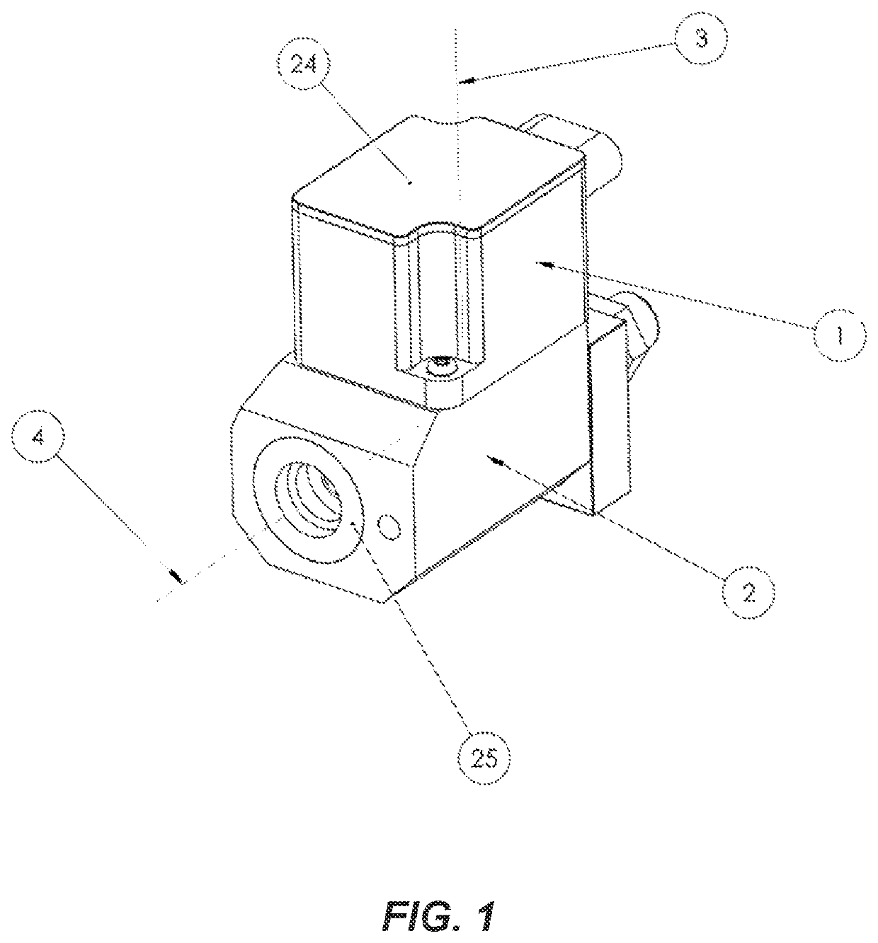
[0045]FIG. 1 is an isometric view of a first embodiment of a valve according to the present disclosure that links an electrical actuation assembly and a mechanical assembly, creating a circulation path for a heat transport fluid. More specifically, the valve thus consists of an electrical actuator (1), which, by means of a rotor rotating around the rotational axis (3), rotates a mechanical shaft having a thread (not visible here). The actuator (1) is fixed to the valve body (2), which comprises the passage channels (25) of a heat transport fluid, the flow rate of which is managed by a needle. The needle of the valve (not shown here) and the elements of the reducer other than the mechanical shaft linked to the rotor, are positioned along an axis (4) that is not parallel to the axis (3). The electrical actuator (1) has a cap (24) on the upper part and is fixed to the valve body (2). The solution presented here is thus more compact along the axis (4) of the needle than those from the p...


PUM


Abstract

A valve for controlling the circulation of a fluid, having a valve body comprising a movable control member, an electrical actuator comprising a stator and a rotor, a sealing cover extending from the valve body to the inside of the stator, the sealing cover being positioned at the interface between the rotor and the stator in such a way that the rotor is inside the cover and submerged in the fluid, the stator being isolated from the fluid, the rotor rotating about a first axis and being secured to a shaft extending along the first axis, the movable control member moving in a linear manner along a second axis or in rotation about the second axis, characterized in that the shaft has an end forming, with a toothed wheel driving the movable control member, a gear pair with non-intersecting or intersecting axes.

Description

CROSS-REFERENCE TO RELATED APPLICATIONS[0001]This application is a national phase entry under 35 U.S.C. § 371 of International Patent Application PCT / FR2020 / 051072, filed Jun. 19, 2020, designating the United States of America and published as International Patent Publication WO 2020 / 254772 A1 on Dec. 24, 2020, which claims the benefit under Article 8 of the Patent Cooperation Treaty to French Patent Application Serial No. 1906660, filed Jun. 20, 2019.TECHNICAL FIELD[0002]The present disclosure relates to a compact control valve intended to control the circulation of a fluid, either liquid or gaseous, for example, as an expansion device for an air conditioning circuit, which valve is actuated by a brushless electrical motor.BACKGROUND[0003]The present disclosure is preferably for, but not limited to, the field of flow control valves for air conditioning or battery cooling circuits. The distinctive feature of these systems is the need to keep the heat transport fluid in a sealed circ...

Claims


Application Information

Patent Timeline
IPC IPC(8): F16K31/04F25B41/35F16K37/00
CPCF16K31/047F25B41/35F16K37/0033F16K31/043F16K31/04F16K31/041F16K31/53F16K31/535F16K31/50F25B41/31Y02B30/70
Inventor BILLET, LIONEL
Owner MOVING MAGNET TECH
Why Eureka
Try Eureka