
Apparatus and methods using the apparatus for treating metal wire

a technology of metal wire and apparatus, applied in the direction of metal rolling arrangement, etc., can solve the problems of unusable stops of the machine, rupture of the wire, and the straightener only adjusting the curvature of the wire in a single plan

Pending Publication Date: 2022-10-13
NV BEKAERT SA
View PDF4 Cites 0 Cited by
  • Summary
  • Abstract
  • Description
  • Claims
  • Application Information

AI Technical Summary

Benefits of technology

This patent aims to simplify the process of adjusting equipment used to treat metal wire by multiple reverse bending. It reduces the complexity of the equipment and the number of adjustable parameters needed. It also simplifies the process of threading the equipment, making it applicable to a wide range of wire diameters without needing adjustments. The invention also includes a method for operating the equipment and a design for the rollers that allows for individual or collective movement, making the apparatus more compact and easier to thread. The use of multiple bending paths with larger contact angles allows for a more compact design.

Problems solved by technology

However, before processing the wire to its final shape it is many times necessary to deliver the wire in a condition that allows this final processing.
Not straight or bent wire can lead to misalignment and undesirable stops of the machine.
Indeed, a straightener can only adjust the curvature of the wire in a single plane.
Due to the repeated bending and back bending of the wire any flaw due to a surface defect or an inclusion will lead to a rupture of the wire.
The selection of number of rollers, the choice of the roller diameters in function of the wire diameter and the setting of the indentation of the rollers, offer a very large parameter space wherein the skilled person readily gets lost.

Method used


Image

  • Apparatus and methods using the apparatus for treating metal wire
  • Apparatus and methods using the apparatus for treating metal wire
  • Apparatus and methods using the apparatus for treating metal wire

Examples


Embodiment Construction

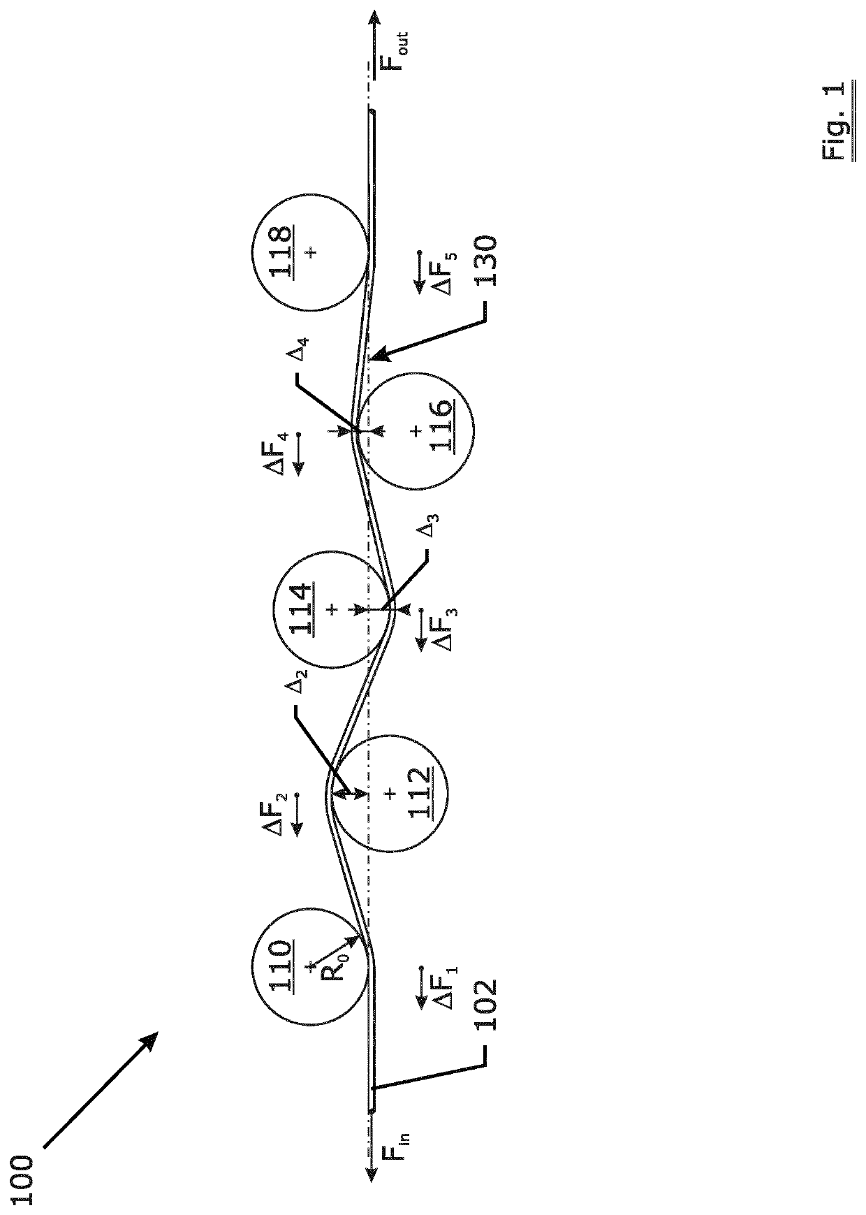
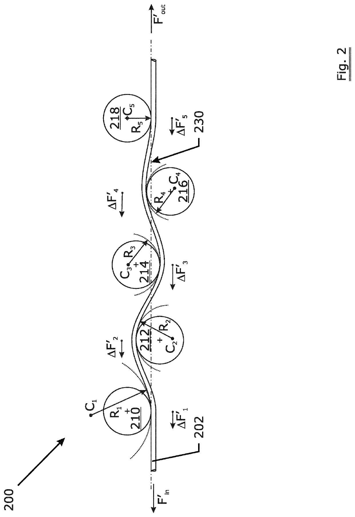
[0062]In FIGS. 1 and 2 the problems with the prior art straighteners is illustrated. In FIG. 1 a straightener 100 with five rollers 110, 112, 114, 116, 118 is depicted that is wired with a small diameter wire 102. All rollers are provided with a groove through which the wire runs. All rollers have the same diameter. The wire is pulled through the device with a pull-through force ‘Fout’ at speed V. The power needed to pull the wire through the straightener is ‘Fout v’. At the entry a pull-back force ‘Fin’ is applied to keep the metal wire in the straightener.

[0063]The radius R0 shown is the radius of curvature taken by the metal wire as it passes the roller 110. In this case—as the wire diameter is small hence the bending stiffness is low—the wire accurately follows the curvature of all the rollers. The bending stiffness ‘(EI)’ (in Nmm2) of a wire is proportional to its material modulus ‘E’ (in N / mm2) and the second axial moment of area ‘I’ (in mm4) that for a round wire with diamete...


PUM

PropertyMeasurementUnit
Thicknessaaaaaaaaaa
Thicknessaaaaaaaaaa
Contact angleaaaaaaaaaa

Abstract

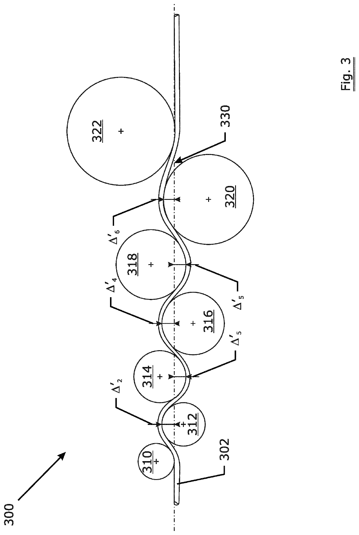
An apparatus for treating metal wire by multiple reverse bending and associated methods for using the apparatus are disclosed. The first roller has a first roller diameter, is followed by N−1 intermediate rollers with intermediate roller diameters and ends with an exit roller with an exit roller diameter. The exit roller is larger than the first roller and any one roller in the sequence of rollers has a roller diameter that is not smaller than the preceding roller in the sequence. The progressively larger diameters impose a well-controlled, gradually decreasing curvature to the wire resulting in a cast controlled wire. By folding the wire path together, a compact arrangement is obtained accommodating the increasingly larger rollers. A method to operate the apparatus is also described that allows for an easy adjustment of the apparatus in function of wire thickness.

Description

TECHNICAL FIELD[0001]The invention relates to an apparatus for treating metal wire by multiple reverse bending of the wire. Such apparatus is also commonly known as a ‘wire straightener’, ‘straightener block’, ‘straightening device’.BACKGROUND ART[0002]Metal wires allow—due their elastic plastic behaviour—forming by stretching, bending and torqueing in almost any desired shape. However, before processing the wire to its final shape it is many times necessary to deliver the wire in a condition that allows this final processing.[0003]In the case of for example nail stamping or spring forming the wire is first made straight in order to allow a precise entry into the machine. Not straight or bent wire can lead to misalignment and undesirable stops of the machine.[0004]The wire shape is generally controlled by guiding the wire through a device called ‘straightener’. Such a device is a series of equal diameter rollers that induce bends to the metal wire in consecutive opposite directions ...

Claims


Application Information

Patent Timeline
IPC IPC(8): B21B1/18
CPCB21B1/18B21F1/004B21F23/00B21F1/02B21D3/05
Inventor DE KEMPE, GEERT
Owner NV BEKAERT SA
Learn More