Compacting roller with an electronic balancing system for maintaining the roller in an upright position

a technology of upright position and roller, applied in the field of compact roller, can solve the problems of cumbersome service and maintenance of such a roller, complex design of the roller,

Pending Publication Date: 2022-10-27
DYNAPAC COMPACTION EQUIP
View PDF0 Cites 2 Cited by
  • Summary
  • Abstract
  • Description
  • Claims
  • Application Information

AI Technical Summary

Problems solved by technology

However, this roller is considered to have a complex design.
Also, it may be

Method used


Image

  • Compacting roller with an electronic balancing system for maintaining the roller in an upright position
  • Compacting roller with an electronic balancing system for maintaining the roller in an upright position
  • Compacting roller with an electronic balancing system for maintaining the roller in an upright position

Examples


Embodiment Construction

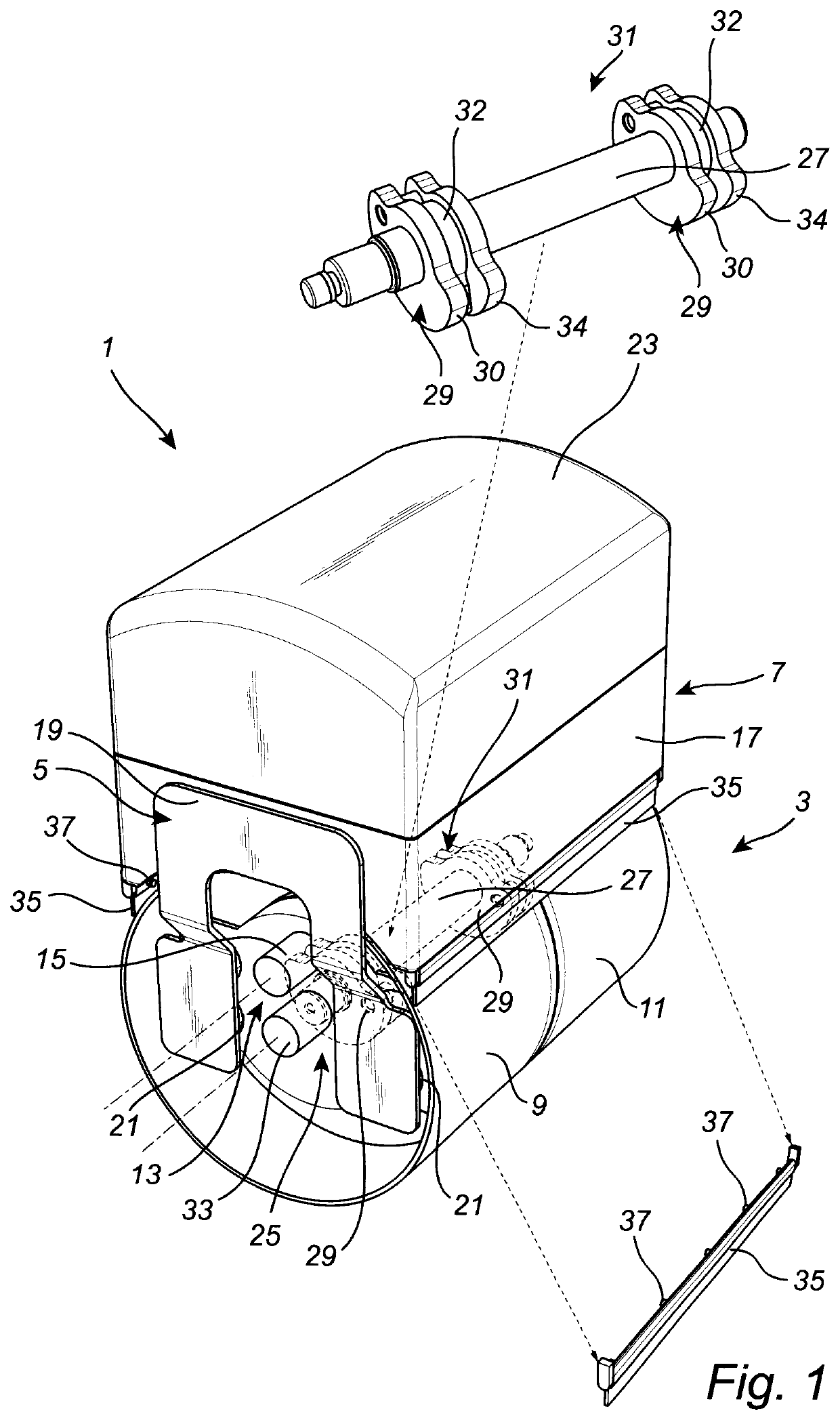
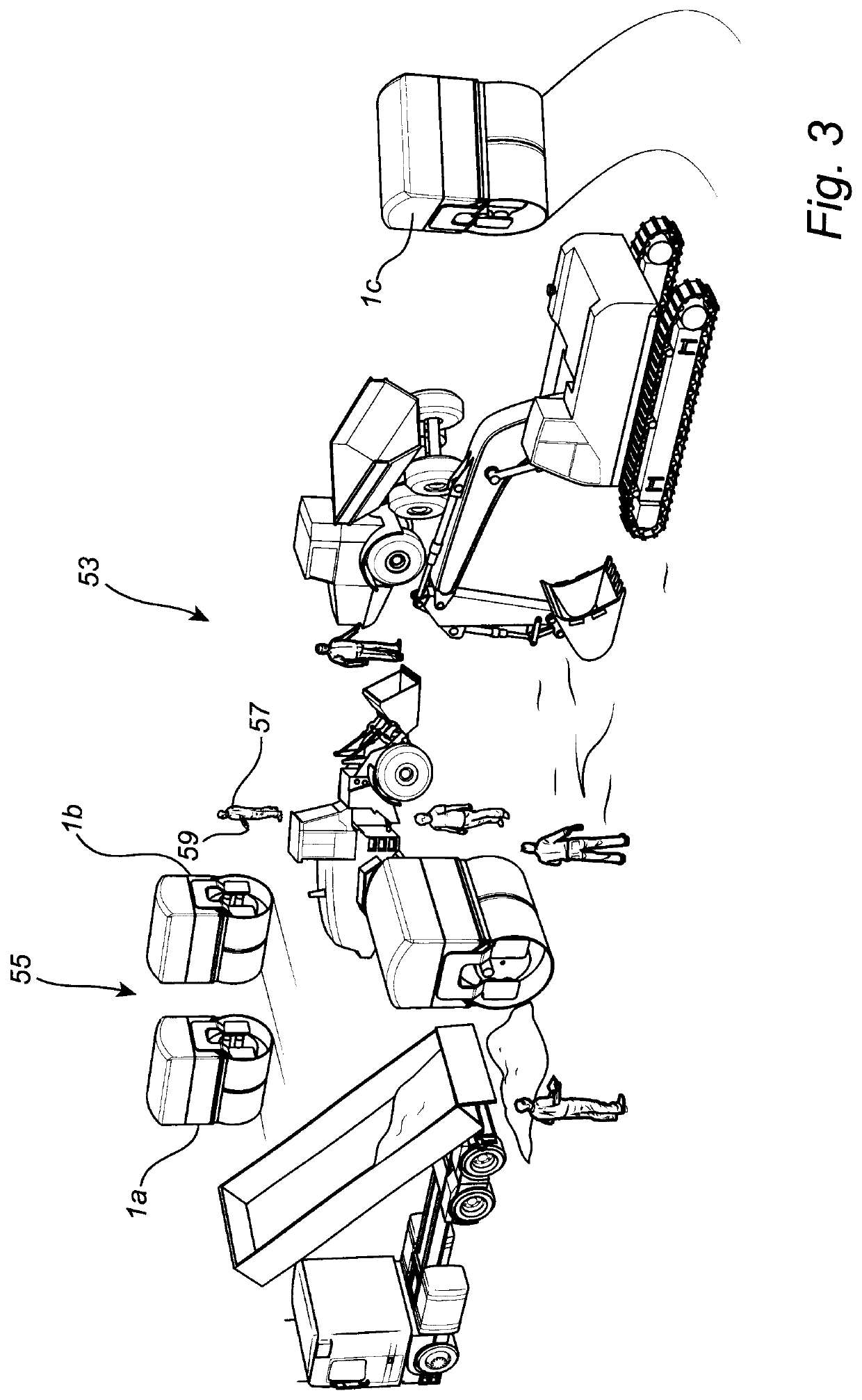
[0026]FIG. 1 illustrates a compacting roller, in the form of an autonomous vibratory roller 1, according to an embodiment of the present disclosure.

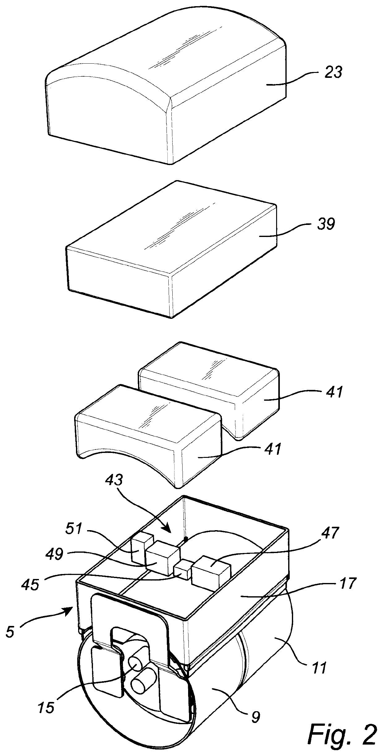
[0027]The vibratory roller 1 comprises a roller drum arrangement 3, a frame 5, which is connected to the roller drum arrangement 3, and a housing 7.

[0028]The roller drum arrangement 3 comprises a first roller drum 9 and a second roller drum 11 arranged next to each other in a split configuration allowing independent rotation of the first roller drum 9 and the second roller drum 11.

[0029]The vibratory roller 1 further comprises a drive arrangement 13 for driving each of the first drum roller 9 and the second drum roller 11. To this end, the drive arrangement 13 comprises a first drive unit 15 arranged to rotate the first roller drum 9 and a second drive unit (not shown) arranged to rotate the second roller drum 11. Each of the first drive unit 15 and the second drive unit is connected to a power supply situated in the housing 7.

[0030]The ...


PUM


Abstract

The present invention relates to a compacting roller (1) comprising a roller drum arrangement (3) comprising a first roller drum (9) and a second roller drum (11) arranged next to each other, a drive arrangement (13) comprising a first drive unit (15) arranged to rotate said first roller drum (9) and a second drive unit arranged to rotate said second roller drum (11), and a power supply (39). The compacting roller by further comprises a frame (5) which is connected to said roller drum arrangement (3), wherein said power supply (39) is attached to said frame (5) outside each of the first roller drum (9) and the second roller drum (11), and an electronic balancing system (43) for maintaining the compacting roller (1) in an upright position during operation.

Description

TECHNICAL FIELD OF THE INVENTION[0001]The present invention relates to a compacting roller comprising a roller drum arrangement comprising a first roller drum and a second roller drum arranged next to each other, a drive arrangement comprising a first drive unit arranged to rotate said first roller drum and a second drive unit arranged to rotate said second roller drum.BACKGROUND ART[0002]Compacting rollers are widely used to compact soil and asphalt e.g. in the construction of roads and buildings.[0003]WO 2018 / 234844 A1 illustrates a compacting roller having two cylindrical drums positioned next to each other. The roller is driven by one or more motors positioned within the cylindrical space defined by the cylindrical drums. The compacting roller further includes a counterweight positioned within the cylindrical space defined by the cylindrical drums.[0004]However, this roller is considered to have a complex design. Also, it may be considered cumbersome to carry out service and mai...

Claims


Application Information

Patent Timeline
IPC IPC(8): E01C19/28
CPCE01C19/283E01C19/286E01C19/282E01C19/26
Inventor CHRISTENSEN, HANS
Owner DYNAPAC COMPACTION EQUIP
Why Eureka
Try Eureka