Transport Apparatus

Pending Publication Date: 2022-11-17
DAIFUKU CO LTD
View PDF0 Cites 0 Cited by
  • Summary
  • Abstract
  • Description
  • Claims
  • Application Information

AI Technical Summary

Benefits of technology

The invention provides a transfer device with a pusher and a lockable portion that can be used to deliver and pick-up containers. The device can easily shorten the time required for the delivery operation and make it easier to implement a configuration suitable for both delivery and pick-up operations. The pusher is used for the delivery operation and the lockable portion is used for pick-up. The device can drive the lockable portion separately from the pusher to change its orientation and move the container towards the pick-up side during the pick-up operation. This reduces the time required to deliver the container. Overall, this invention simplifies the process of delivering and picking-up containers.

Problems solved by technology

However, members having a shape such as that of the hooks (30, 32, 34, 36) disclosed in Patent Document 1 are not necessarily suitable to use in the delivery operation, although they are suitable to use in the pick-up operation.

Method used


Image

  • Transport Apparatus
  • Transport Apparatus
  • Transport Apparatus

Examples


Embodiment Construction

[0054]A transport apparatus is an apparatus that transports containers. The following describes an embodiment of a transport apparatus with reference to an example in which the transport apparatus is provided in a transport facility in which containers are transported.

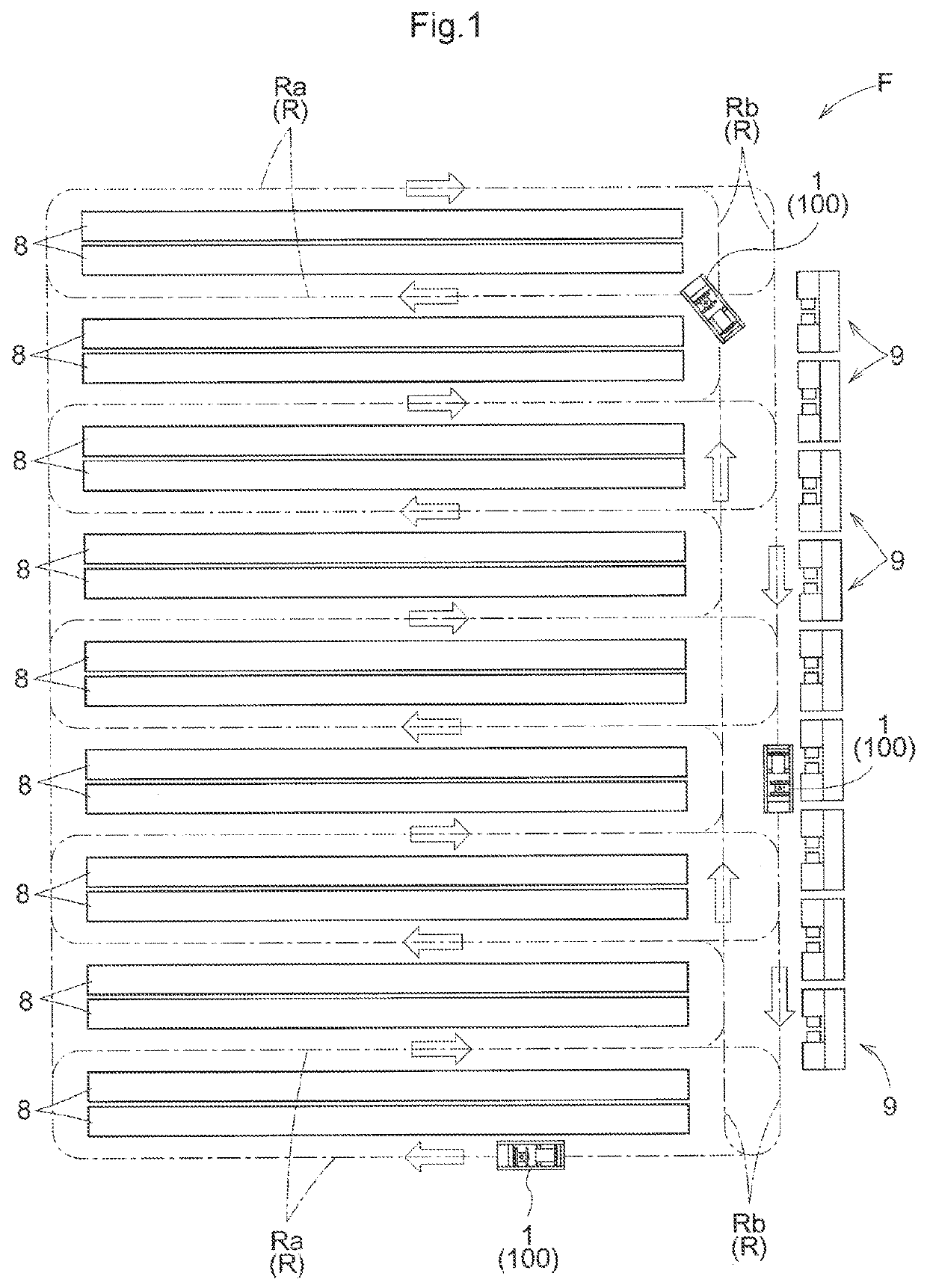
[0055]A transport facility F includes container racks 8 for storing containers 70 (see FIGS. 3 and 4), and loading / unloading sections 9 for loading containers 70 into the transport facility F and unloading the containers 70 from the transport facility F, as shown in FIG. 1. Transport apparatuses 100 transport the containers 70 loaded through the loading / unloading sections 9 to the container racks 8, or transport the containers 70 stored in the container racks 8 to the loading / unloading sections 9 for unloading.

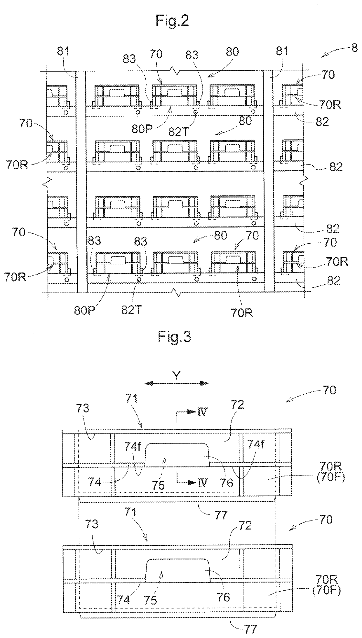
[0056]In the present embodiment, a plurality container racks 8 are arranged parallel to each other with regular spacings. Each of container racks 8 is open at least in a front face thereof. The containers 70 are ...


PUM


Abstract

A transfer device includes: a pusher configured to push a container during a delivery operation; a lockable portion lockable to the container during a pick-up operation; a transfer drive unit configured to cause the pusher and the lockable portion to reciprocate in the transfer direction; and a lock drive unit configured to drive the lockable portion separately from the pusher and causes the lockable portion to change in orientation. The transfer device performs a delivery operation by moving, toward a delivery side in the transfer direction, the pusher in contact with a container rear face portion with use of the transfer drive unit, and performs a pick-up operation by moving the lockable portion in the locking orientation toward a pick-up side in the transfer direction with use of the transfer drive unit.

Description

CROSS-REFERENCE TO RELATED APPLICATION[0001]This application claims priority to Japanese Patent Application No. 2021-081803 filed May 13, 2021, the disclosure of which is hereby incorporated by reference in its entirety.BACKGROUND OF THE INVENTION1. Field of the Invention[0002]The present invention relates to a transport apparatus that transports containers.2. Description of the Related Art[0003]JP 6337706B (Patent Document 1) discloses an example of a transfer device for transporting items to storage racks. In the following, the reference numerals in parentheses in the description of the background section are those used in Patent Document 1.[0004]A transfer device (2) disclosed in Patent Document 1 has package placement sections (26) on which an item (10) is placeable, and a slide arm (28) having a plurality of hooks (30, 32, 34, 36). The transfer device (2) performs a delivery operation to transfer an item (10) from the placement sections (26) to a rack (12a, 12b) and a pick-up o...

Claims


Application Information

Patent Timeline
IPC IPC(8): B66F9/19B66F9/18
CPCB66F9/195B66F9/18B65G1/04B66F9/07B66F9/141B66F9/0755B65G1/0492B65G1/1375B65G1/0485
Inventor IWATA, MASASHIGEKIMURA, KAZUNARIMURATA, HIROYOSHI
Owner DAIFUKU CO LTD
Why Eureka
Try Eureka