Method for manufacturing conveyance device

Pending Publication Date: 2022-04-14
ITO DENKI KK
View PDF0 Cites 0 Cited by
  • Summary
  • Abstract
  • Description
  • Claims
  • Application Information

AI Technical Summary

Benefits of technology

The present invention is a method for manufacturing a conveyance device that allows the customer to visually recognize the motion of the device. This helps to avoid any discrepancies in recognition between the manufacturer and the customer. The method also allows for easy creation of a completed specification and implementation of a virtual operation confirmation step. The invention can accurately complete the conveyance device imagined by the customer in a relatively short time.

Problems solved by technology

The conventional methods for manufacturing a conveyance device have problems that many correction operations are needed after the conveyance device is installed.
However, the customer is not always familiar with a structure or motion of the conveyance device, and it is difficult to understand the motion of the conveyance device.
For example, even if the manufacturer explains that “the conveyance speed is 200 meters per minute”, it is difficult for the customer to understand how fast the conveyance speed is in an actual condition.
Therefore, there may be a discrepancy in understanding between the customer and the manufacturer at a stage of specification determination.
Further, when the object is actually conveyed, an unexpected error may occur.
Thus, in the prior art method for manufacturing a conveyance device, there need many corrections of the program or the like after the test run, and a considerable period of time may be required until delivery from the manufacturer to the customer.
After the delivery to the customer, there is a case where the customer requests correction of motion whether an error occurs or not, and it may take a considerable period of time to correct the computer program or the like.

Method used


Image

  • Method for manufacturing conveyance device
  • Method for manufacturing conveyance device
  • Method for manufacturing conveyance device

Examples


Embodiment Construction

[0067]Hereinafter, an embodiment of the present invention will be described in detail.

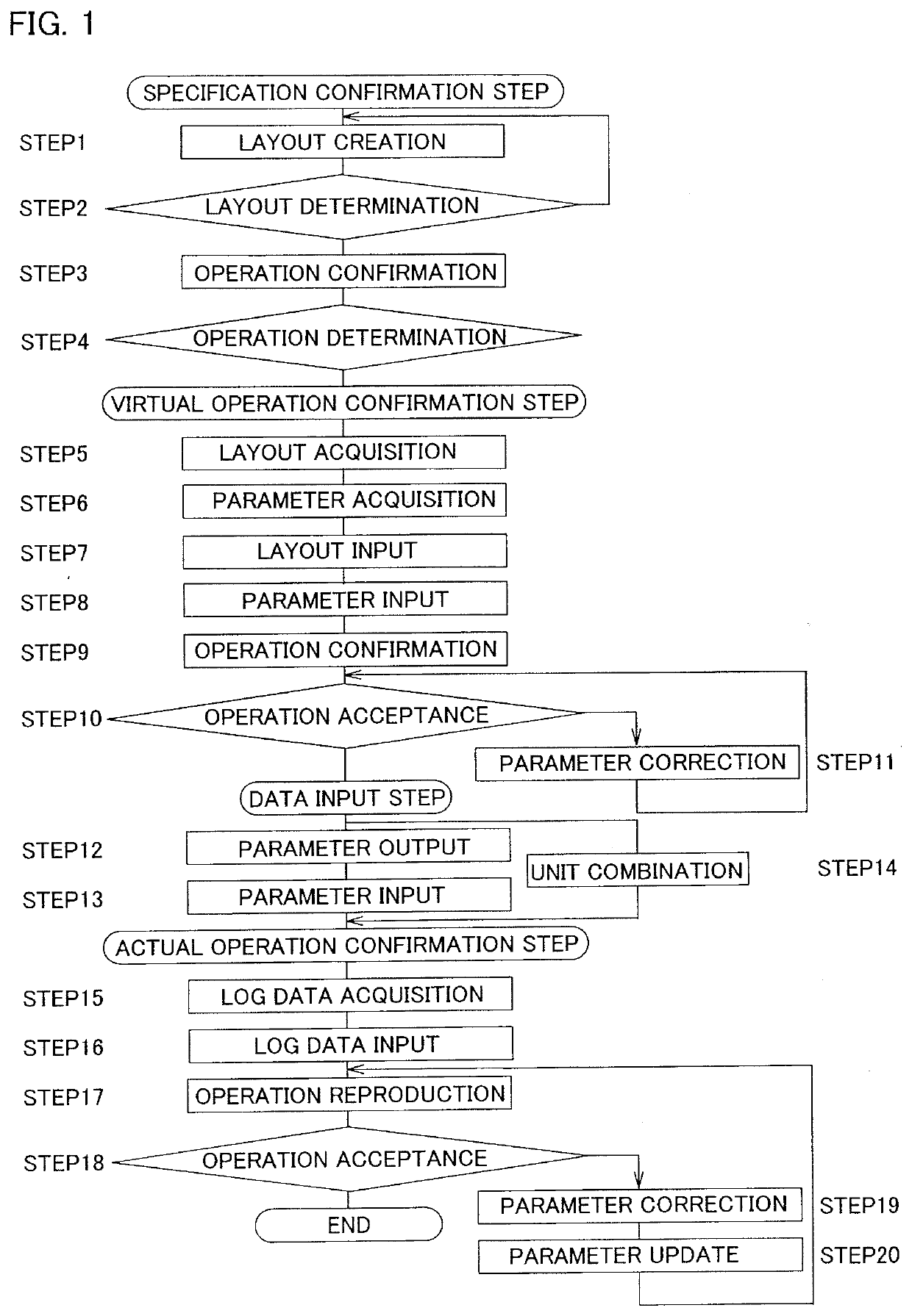
[0068]A method for manufacturing a conveyance device according to the present embodiment completes the conveyance device through the following steps (see FIG. 1).

[0069](1) Specification Confirmation Step[0070]a: Layout creation step[0071]b: Operation confirmation step

[0072](2) Virtual Operation Confirmation Step[0073]a: Layout acquisition step[0074]b: Layout input step[0075]c: Parameter acquisition step[0076]d: Parameter input step[0077]e: Operation confirmation step[0078]f: Parameter correction step

[0079](3) Data Input Step[0080]a: Parameter output step[0081]b: Parameter input step[0082]c: Unit combination step

[0083](4) Actual Operation Confirmation Step[0084]a: Log data acquisition step[0085]b: Log data input step[0086]c: Operation reproduction step[0087]d: Parameter correction step

[0088](5) Data Correction Step[0089]a: Parameter update step

[0090]Subsequently, the following steps are performed.

[0...


PUM


Abstract

Provided is a method for manufacturing a conveyance device capable of accurately completing the conveyance device imagined by a customer in a relatively short time. In a method for manufacturing a conveyance device, one or a plurality of operation confirmation devices that visually confirms an operation of the conveyance device is used, the method includes exhibiting a desired operation of the conveyance device in a video by the operation confirmation device and confirming a required operation of the conveyance device in a specification confirmation step, inputting data for realizing the required operation or realizing an operation similar to the required operation to the operation confirmation device, and exhibiting the operation of the conveyance device in a video based on the data that has been input in a virtual operation confirmation step, and inputting the data to an actual individual controller of the conveyance unit in a data input step.

Description

BACKGROUND OF THE INVENTIONField of the Invention[0001]The present invention relates to a method for manufacturing a conveyance device such as a conveyer device.Background Art[0002]A conveyance device is often installed in a delivery site, a pickup site, a warehouse, or the like.[0003]As a form of the conveyance device, a distributed-control conveyance device is known (Patent Document 1). In distributed control, a plurality of conveyance units called zone conveyers are arranged in series or in branches to form a series of conveyance paths, and each conveyance unit has an independent drive motor (drive device). Each conveyance unit is provided with a load presence sensor. The load presence sensor is a sensor that detects presence or absence of an article on the conveyance unit. Each conveyance unit is provided with a control device called a zone controller. The controller incorporates a CPU 201 and a storage unit, and the storage unit stores a computer program (data) constituting a l...

Claims


Application Information

Patent Timeline
IPC IPC(8): B65G43/10
CPCB65G43/10B65G2203/044B65G2203/0291G06F30/17G06F30/20G06F2113/20G05B19/41885G05B2219/50393G05B2219/23452G05B2219/23455G05B2219/23456G05B2219/32357G05B2219/32351G05B2219/45054G05B19/4189Y02P90/02
Inventor ITOH, KAZUOTACHIBANA, TOSHIYUKIINOUE, MITSUOTAKANAGA, AKIRA
Owner ITO DENKI KK
Why Eureka
Try Eureka