Selvedge-forming device with independent control and eccentric drive system

a technology of eccentric drive and selvageforming device, which is applied in the direction of looms, leno shedding mechanism, textiles and paper, etc., can solve the problem of fairly complex drive, and achieve the effect of low cost, low cost and low production cos

Inactive Publication Date: 2000-01-04
PICANOL NV
View PDF3 Cites 7 Cited by
  • Summary
  • Abstract
  • Description
  • Claims
  • Application Information

AI Technical Summary

Benefits of technology

The invention makes it possible to change the weave of selvage yarns and inserted fillings in a simple manner in the case of consecutive filling insertions because only the drive control need be changed. As regards consecutive insertions of fillings, the number of fillings interlaced with the selvage yarns and/or the kind of mutual crossing of selvage

Problems solved by technology

The drive is f

Method used


Image

  • Selvedge-forming device with independent control and eccentric drive system
  • Selvedge-forming device with independent control and eccentric drive system
  • Selvedge-forming device with independent control and eccentric drive system

Examples


Embodiment Construction

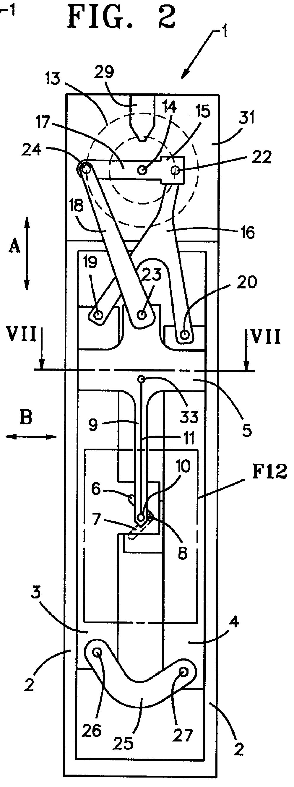
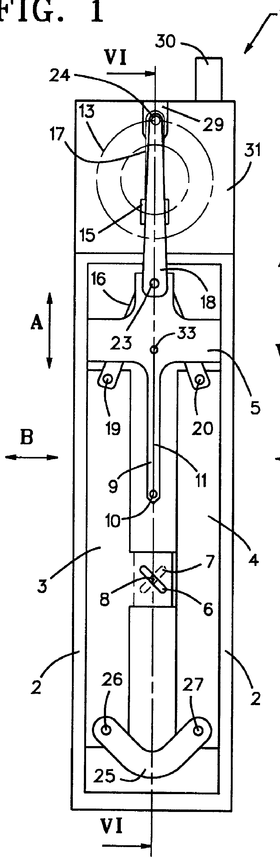
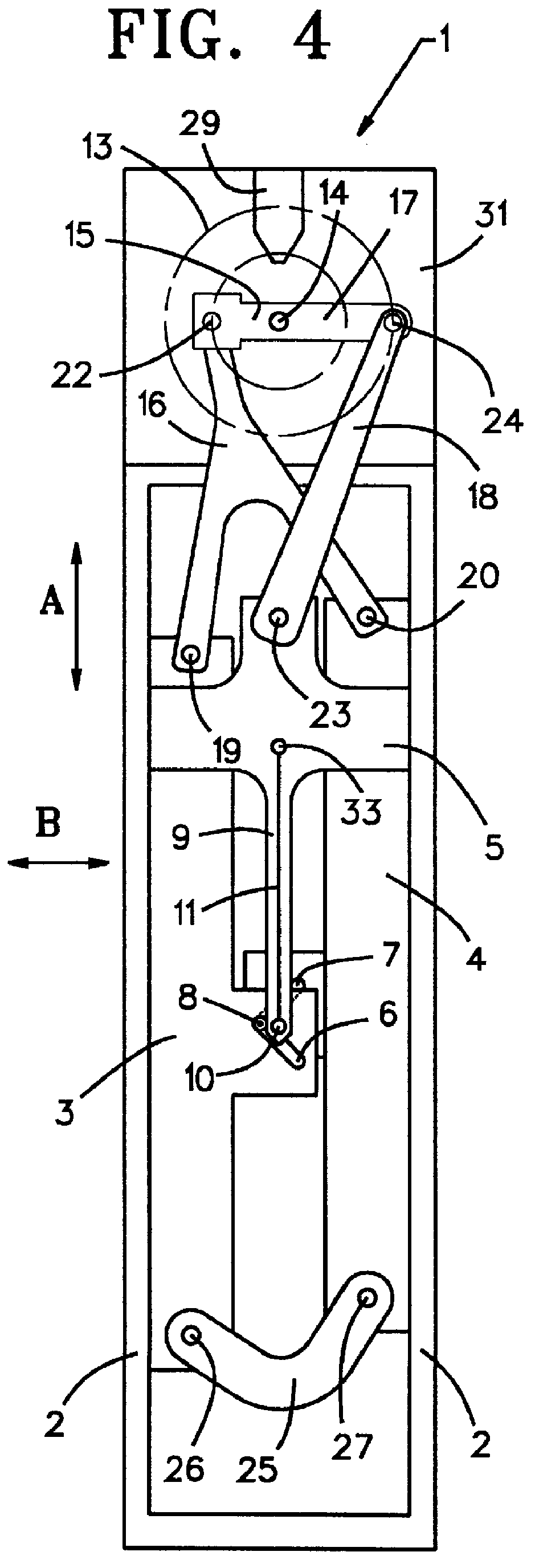
The selvage-forming device 1 shown in FIGS. 1 through 7 comprises two lateral guide segments 2 within which three yarn guide structures or devices 3, 4 and 5 are guided in the longitudinal or vertical (up and down) direction A. Two selvage yarns 8 and 11, each from a particular yarn supply, especially a bobbin, are consecutively raised and lowered in the longitudinal direction A in order to subtend consecutive selvage sheds 12 (FIG. 6). The yarn guide structures 3 and 4 each contain a slot 6, 7. The slots 6, 7 of the consecutively mounted yarn guide structures 3, 4 run in mutually opposite directions and obliquely to the longitudinal direction A. The slots 6, 7 guide a selvage yarn 8. When the yarn guide structures 3, 4 and hence the slots 6, 7 are moved mutually oppositely in the longitudinal direction A, the slots 6, 7 move the selvage yarn 8 in the transverse direction B, that is transversely to the longitudinal direction A. The yarn guide structure 5 contains a needle 9 fitted a...


PUM


Abstract

PCT No. PCT/EP97/00495 Sec. 371 Date Nov. 20, 1998 Sec. 102(e) Date Nov. 20, 1998 PCT Filed Feb. 4, 1997 PCT Pub. No. WO97/29232 PCT Pub. Date Aug. 14, 1997A selvage-forming device (1) for a loom includes yarn guide structures (2, 3, 5) to guide at least two selvage yarns (8, 11) that are alternating raised and lowered to form a selvage shed (12). These yarn guide structures are powered through the intermediary of eccentrics driven by their own independently controlled drive (13) and an eccentric drive coupling-bracket (16) that creates a motion by which one selvage yarn (8) is additionally shifted transversely to form mutually crossing interlacings.

Description

1. Field of the InventionThe invention relates to a selvage-forming device for a power loom, with yarn guide structures to raise and lower at least two selvage yarns.2. Related ArtSelvage-forming devices cooperating with selvage yarns are used in looms to form a fabric selvage or a waste band. The selvage yarns are guided in yarn guide structures which raise and lower these yarns to subtend sheds in which the fillings are laced into the selvage yarns in a predetermined pattern. The yarn guide structures usually are fitted with yarn guide elements in the form of circular, oval or slotted apertures. The selvage yarns also are called catch threads.Selvage-forming devices for at least two selvage yarns are known. Therein a first selvage yarn is moved up and down in one plane while a second selvage yarn is moved up and down in the opposite direction to the first one and simultaneously is displaced transversely to the plane of the up-and-down motion, whereby the two selvage yarns cross ea...

Claims


Application Information

Patent Timeline
IPC IPC(8): D03C7/00D03D47/40D03C7/06D03D47/00
CPCD03C7/06D03D47/40
Inventor MEYNS, IGNACESLOSSE, KURT
Owner PICANOL NV
Why Eureka
Try Eureka