

Fluid actuator system having means for internally increasing the fluid pressure therein
- Summary
- Abstract
- Description
- Claims
- Application Information
AI Technical Summary
Benefits of technology
Problems solved by technology
Method used
Image

Examples
Embodiment Construction
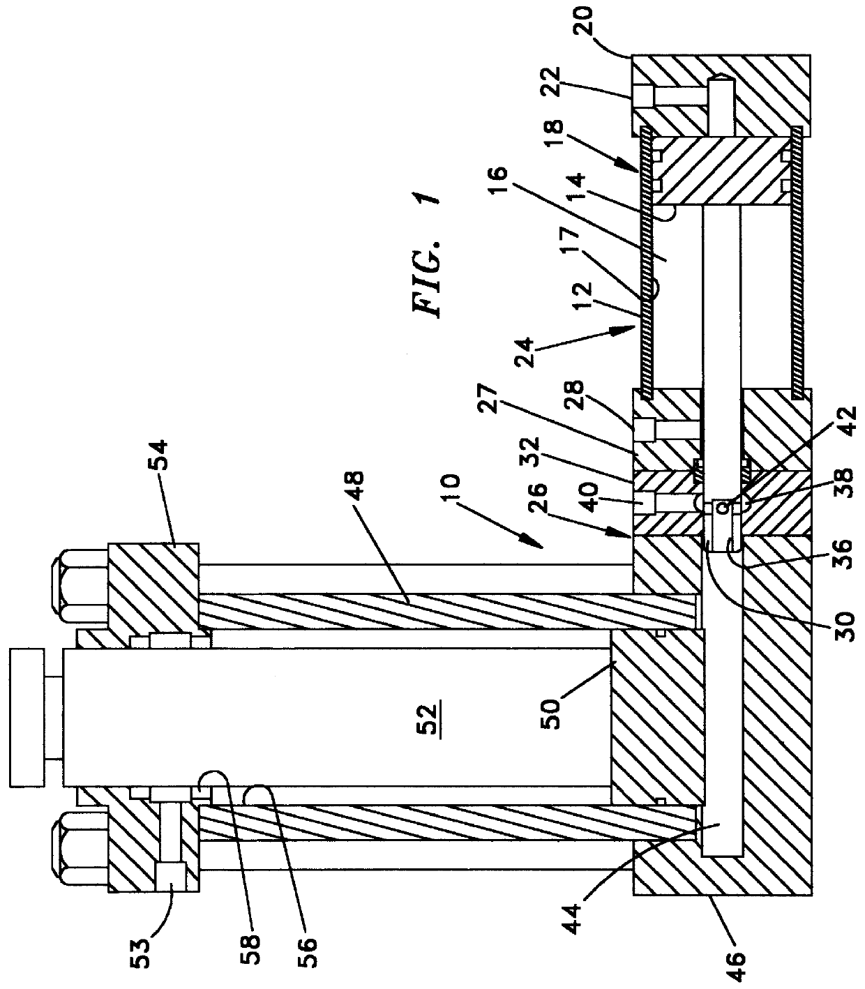
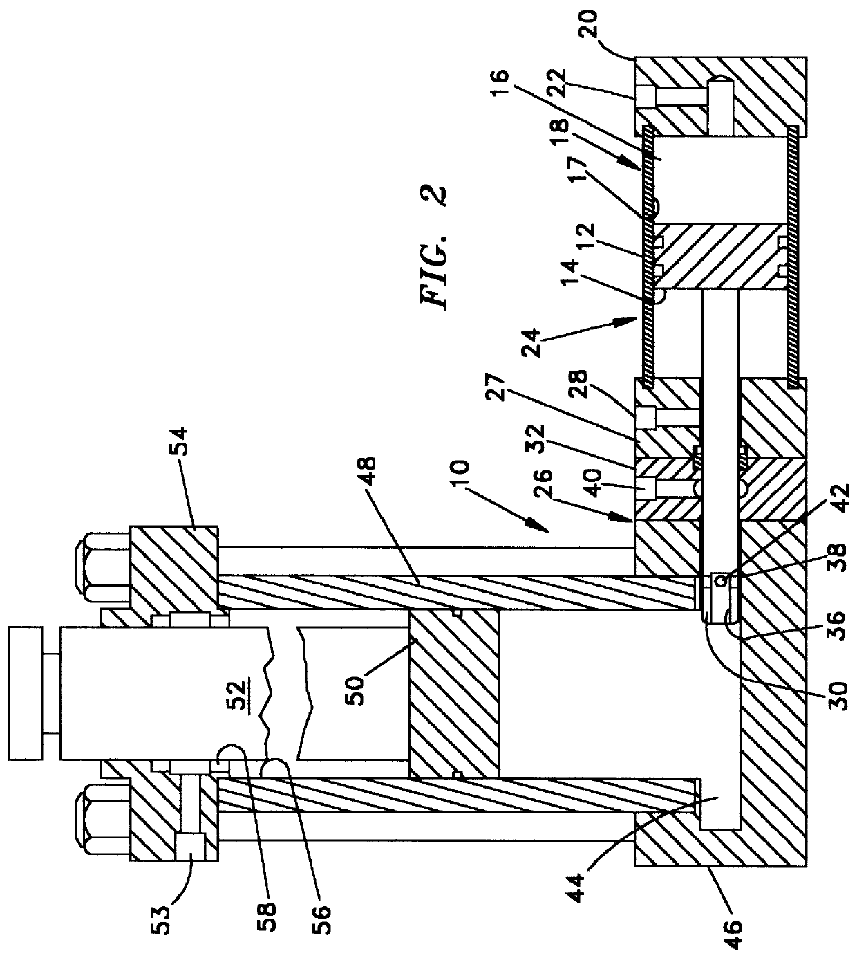
As seen in FIG. 1, a fluid actuator system 10 is shown to include a first cylinder 12 enclosing a piston 14 and piston rod 16, which are mounted in a bore 17 of cylinder 12. Cylinder 12 is provided at one end 18 with an end closure member 20 having a fluid passage 22 therein. At the second end 24 of cylinder 12 is an end closure assembly 26 including a rod supporting member 27 having a fluid passage 28 therein. Fluid passages 22 and 28 communicate into bore 17 on opposite sides of piston 14.
Piston rod 16 includes an end portion 30 which extends out of cylinder 12 and into end closure assembly 26. A piston rod support member 32 is provided in closure assembly 26 for support of end portion 30 of piston rod 14. An axial bore 36 is provided in the end portion 30 of piston 14 and an annular port 38 is provided in rod support member 32 into which a fluid passage 40 of rod support member 32 communicates. A plurality of radially extending ports 42 is provided in end portion 30 of piston and...
PUM
 Abstract
Description
Claims
Application Information