Novel piezoelectric pump

A piezoelectric ceramic pump and piezoelectric ceramic technology are applied in the direction of pumps, pumps with flexible working elements, liquid variable capacity machinery, etc., which can solve the problems of small deformation, low efficiency, and low output flow, and achieve output Effects of increased flow rate and output pressure, and improved efficiency

Active Publication Date: 2015-03-18
SHANGHAI XURUN MEDICAL TECH CO LTD
View PDF6 Cites 0 Cited by
  • Summary
  • Abstract
  • Description
  • Claims
  • Application Information

AI Technical Summary

Problems solved by technology

However, since the deformation of the ceramic sheet fixed by the surrounding support must first overcome the limitation of the support on the deformation of the ceramic sheet, the energy required for the deformation movement is large and the deformation amount is small, so the output flow rate is low and the efficiency is not high.

Method used


Image

  • Novel piezoelectric pump
  • Novel piezoelectric pump
  • Novel piezoelectric pump

Examples


Embodiment approach 1

[0014] Square or rectangular pump cavity, square or rectangular piezoelectric vibrator terminal fixed

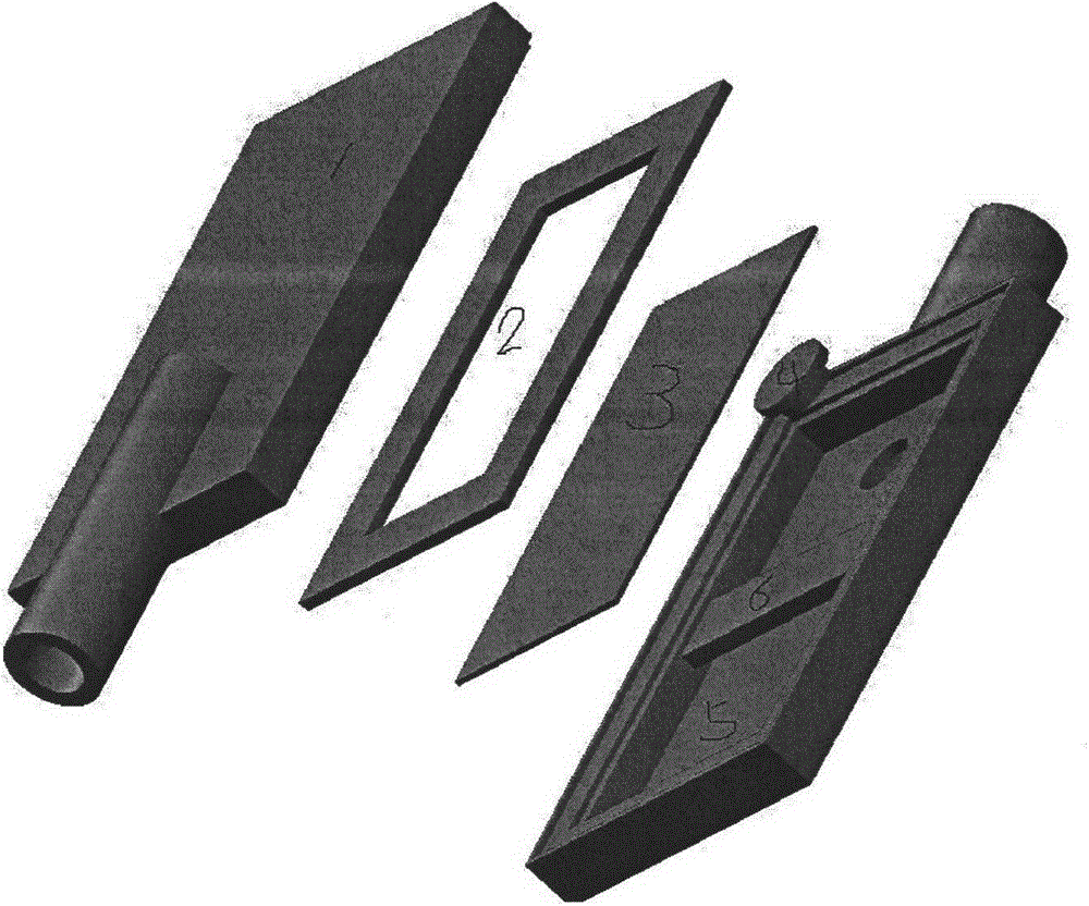
[0015] figure 2 : 1 Lower housing 2 One-way sealing ring 3 Piezoelectric vibrator 4 One-way valve membrane 5 Upper housing

[0016] The pump casing is composed of upper and lower parts, and there is a square or rectangular groove in the middle of the upper and lower casings. The width of the piezoelectric vibrator piece is smaller than the width of the housing slot, and the length is greater than the length of the housing slot. The one-way sealing ring is sandwiched between the upper and lower housings, and the piezoelectric vibrator piece is located on one side of the one-way sealing ring and is in contact with the one-way sealing ring. The three edges of the piezoelectric vibrator piece maintain a certain gap with the side wall of the groove, and the other side is fixed on the side wall of the groove.

Embodiment approach 2

[0018] Square or rectangular pump cavity, fixed in the middle of square or rectangular piezoelectric ceramics

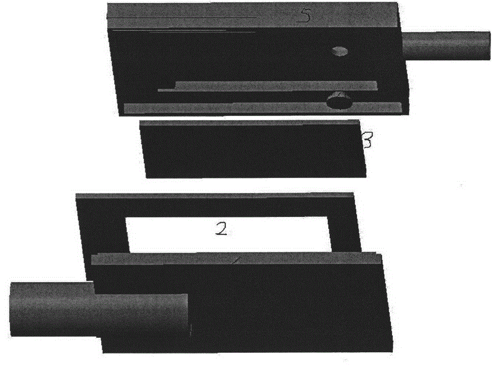
[0019] The pump casing is composed of upper and lower parts, and there is a square or rectangular groove in the middle of the upper and lower casings. There is a beam in the center of the slot for fixing the piezoelectric vibrator piece. The piezoelectric vibrator piece is smaller than the slot on the casing. The one-way sealing ring is sandwiched between the upper and lower housings, and the piezoelectric vibrator piece is located on one side of the one-way sealing ring and is in contact with the one-way sealing ring. A certain gap is maintained between the edge of the piezoelectric vibrator piece and the side wall of the slot.

[0020] image 3 : 1 Lower housing 2 One-way sealing ring 3 Piezoelectric vibrator 4 One-way valve membrane 5 Upper housing

[0021] 6 piezoelectric vibrator fixed beam

Embodiment approach 3

[0023] Circular pump cavity, circular piezoceramic disc, fixed elastic membrane seal at the midpoint

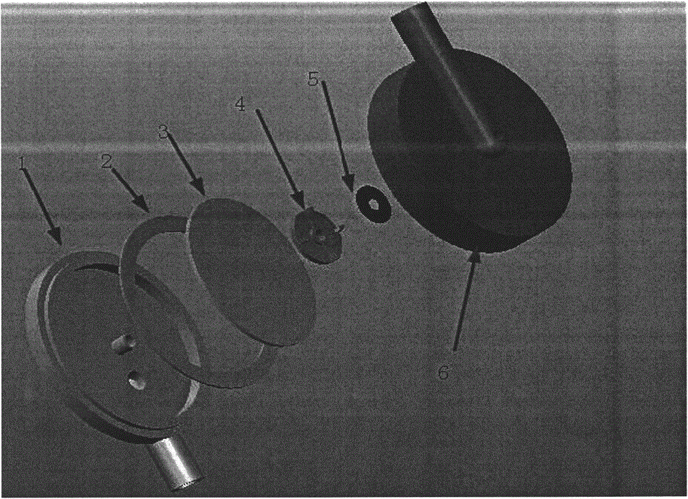
[0024] Figure 4 : 1 upper shell 2 piezoelectric vibrator 3 elastic sealing film 4 one-way valve film 5 lower shell

[0025] The pump casing is composed of upper and lower parts, and there is a circular cavity in the middle of the upper and lower casings. There is an elastic film between the upper and lower shells to divide the cavity into upper and lower parts. The edge of the film is corrugated so that the edge of the film can be fixed between the upper and lower shells and the film itself can vibrate. The piezoelectric vibrator piece is located on one side of the membrane, and its diameter is smaller than that of the cavity. Two one-way valves are arranged on the casing of the cavity on the other side, and the fluid directions are opposite.


PUM

PropertyMeasurementUnit
thicknessaaaaaaaaaa

Abstract

A piezoelectric pump is a revolutionary product of a micro pump manufacturing technology. The piezoelectric pump is simple in structure, small in size, low in weight and low in energy consumption, and causes no noise and no electromagnetic interference. When a ceramic wafer with the periphery supported and fixed deforms, the ceramic wafer needs to overcome a limit of a support on deformation of the ceramic wafer firstly, and energy needed by the ceramic wafer to perform deformation movement is large and deformation quantity of the ceramic wafer is small, and therefore output flow is low, and furthermore efficiency is low. The invention mainly aims at designing a novel piezoelectric ceramic driving piezoelectric ceramic pump which overcomes defects in work of the piezoelectric pump and achieves the purpose of using small energy to obtain high output flow and pressure. The novel piezoelectric ceramic driving piezoelectric ceramic pump is mainly characterized by comprising a piezoelectric vibrator, wherein one end of the piezoelectric vibrator is fixed on a housing or the center of the piezoelectric vibrator is fixed, and other portions of the piezoelectric vibrator are suspended in a cavity and form a cantilever type support. By adopting the above mode, large flexural deformation is generated at the front end of the piezoelectric vibrator, and simultaneously the piezoelectric vibrator is low in resonant frequency. Furthermore, a crack between the periphery of the piezoelectric vibrator and the housing is sealed by a one way seal ring so as to form a double cavity pump, or a space between the periphery of the piezoelectric vibrator and the housing can be sealed by an elastic membrane structure so as to form a typical single cavity pump.

Description

Technical field [0001] The invention belongs to the field of microelectronic fluid machinery, and can be used for micro liquid or gas driven pumps in the technical fields of medical equipment, bioengineering, micro equipment, etc. Specifically, the piezoelectric vibrator is deformed by using the inverse piezoelectric effect of piezoelectric ceramics. A micropump manufacturing technology that realizes fluid output by changing the volume of the pump chamber through deformation. Background technique [0002] Piezoelectric pump is a revolutionary product of micro-pump manufacturing technology. Although its invention and development have only a history of more than 20 years, it can be used according to its simple structure, small size, light weight, low energy consumption, no noise, and no electromagnetic interference. Applied voltage or frequency controls the output of small flow, so it has been successfully applied in many fields. In 1978, W.J.Spenser of the Sandia National La...

Claims


Application Information

Patent Timeline
Patent Type & Authority Applications(China)
IPC IPC(8): F04B43/04
Inventor 席斌
Owner SHANGHAI XURUN MEDICAL TECH CO LTD
Why Eureka
Try Eureka