Electro-hydraulic servo valve suitable for large g value acceleration environment

An electro-hydraulic servo valve and servo valve technology, which is applied to servo motor components, fluid pressure actuating devices, mechanical equipment, etc. The effect of high frequency characteristics, good parallel push performance and large output flow

Inactive Publication Date: 2014-02-19
GENERAL ENG RES INST CHINA ACAD OF ENG PHYSICS
View PDF7 Cites 3 Cited by
  • Summary
  • Abstract
  • Description
  • Claims
  • Application Information

AI Technical Summary

Problems solved by technology

Existing servo valves are used in vibrating tables with large flow rates. Two-stage or three-stage valves need to be selected. When used in a centrifugal environment, due to the centrifugal force, the position of the pilot stage armature and the distance between the nozzle baffles may change. Affect its zero position, symmetry, working range, etc.
For the two-stage and three-stage spool valves, the centrifugal force along the axial direction of the spool will cause the spool to have a large zero offset, resulting in abnormal operation, and also cause the servo valve spool to deviate from zero or increase friction, and the spool will move The required thrust increases, the effective stroke of the spool decreases, and the centrifugal force perpendicular to the axial direction of the spool will cause the spool to bear a large lateral force, resulting in increased friction, inflexible movement of the spool or even stuck, and increased wear speed, which affects life
In short, the centrifugal environment has a great influence on the ordinary servo valve. It can be used directly on the vibration table of the centrifuge. It can still work in the lower acceleration range, and the performance will drop or not work if it is high.

Method used


Image

  • Electro-hydraulic servo valve suitable for large g value acceleration environment
  • Electro-hydraulic servo valve suitable for large g value acceleration environment

Examples


Embodiment Construction

[0017] The present invention will be further described below in conjunction with accompanying drawing:

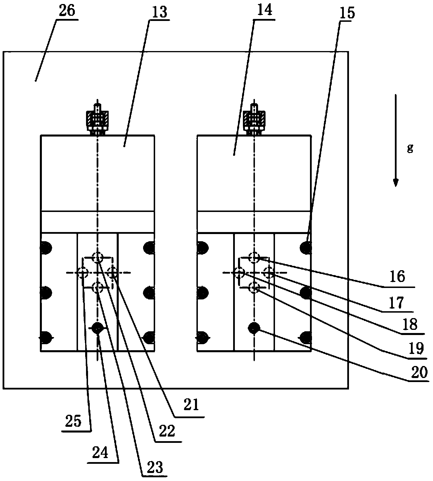
[0018] Such as figure 1 and figure 2 As shown, the present invention is an electro-hydraulic servo valve suitable for a large-g acceleration environment, including a servo valve and a valve block 26, the servo valve includes a first servo valve 13 and a second servo valve 14, and the first servo valve 13 The second servo valve 14 is two servo valves with the same structure and similar performance. The first servo valve 13 and the second servo valve 14 are connected to the valve block 26 through the socket head cap screw 15. The valve block 26 is internally provided with a hydraulic channel 7 for The first servo valve 13 and the second servo valve 14 are communicated for use.

[0019] The specific connection relationship between the hydraulic channel 7 of the first servo valve 13 and the second servo valve 14 is: the P port 22 of the first servo valve communicates with th...


PUM


Abstract

The invention discloses an electro-hydraulic servo valve suitable for a large g value acceleration environment. The electro-hydraulic servo valve comprises a servo valve body and a valve block. The servo valve body comprises a first servo valve body and a second servo valve body. The first servo valve body and the second servo valve body are of the same structure and installed on the valve block side by side. The axial direction of valve cores is the same as the centrifugal acceleration direction of a centrifugal machine. The S port of the first servo valve body is communicated with the S port of the second servo valve body through a channel in the valve block. Through the direct drive mode and the connection mode of the first servo valve body and the second servo valve body, it is guaranteed that the valve core of the first servo valve body and the valve core of the second servo valve body are still located in the neutral position under a centrifugal field, centrifugal force is compensated, high-frequency-response servo control can be provided under the large g value centrifugal field, and the defect that a common servo valve is easily affected by centrifugal acceleration or can not work under the centrifugal environment is overcome; a direct drive large-flow slide valve is adopted, links are few, frequency characteristics are high, and wave form distortion is small.

Description

technical field [0001] The invention relates to an electro-hydraulic servo valve used in an electro-hydraulic servo control system, in particular to an electro-hydraulic servo valve suitable for an acceleration environment with a large g value. Background technique [0002] The model earthquake simulation test on the centrifuge can generate controlled seismic waves at the bottom of the scaled model under the condition of accurately reproducing the stress level of the prototype, and the seismic deformation or failure characteristics of the prototype structure can be obtained by monitoring the seismic response of the scaled model . Most of the shaking table model tests on the centrifuge adopt the electro-hydraulic servo control method on the centrifuge. The electro-hydraulic servo control system requires good stability, high accuracy and fast response speed. The system response speed is related to the operating frequency of the servo valve. For the earthquake simulation scali...

Claims


Application Information

Patent Timeline
Patent Type & Authority Applications(China)
IPC IPC(8): F15B13/02
Inventor 牛宝良刘谦王钰凌明祥李晓琳王宇飞
Owner GENERAL ENG RES INST CHINA ACAD OF ENG PHYSICS
Why Eureka
Try Eureka