Aspherical spectacle lens

a spectacle lens and aphemeral technology, applied in the field of spectacle lenses, can solve the problems of inability to realize free surface, difficult to machine each of the refractive surfaces of the lens in such a manner, and demerits in lens design

Inactive Publication Date: 2000-01-11
HOYA CORP
View PDF8 Cites 34 Cited by
  • Summary
  • Abstract
  • Description
  • Claims
  • Application Information

AI Technical Summary

Problems solved by technology

This is undesirable from the viewpoint of the beauty of the external appearance thereof.
Although there has been proposed an idea of forming the former refractive surface (namely, the axisymmetric surface) in the shape of an aspherical surface in this case (namely, a method of forming each of the refractive surfaces of the lens in the shape of an aspherical surface), it is difficult to machine each of the refractive surfaces of the lens in such a manner.
Thus, such a free surface cannot be realized.
Free curved surface, which is represented by this equation, assures the continuity of a differential of arbitrary order and meets requirements for correcting the astigmatic conditions of the central portion of the lens, However, the excellent analyzability of this two-dimensional equation causes demerits in designing a lens.
Further, in the process of changing such coefficients, owing to the properties of finite power series, the curved surface is liable to undulate (namely, what is call

Method used


Image

  • Aspherical spectacle lens
  • Aspherical spectacle lens
  • Aspherical spectacle lens

Examples


embodiments 2

This embodiment is an example of making an astigmatic lens based on the basic design data listed in the following TABLE 3.

a. Curved Surface by Conventional Technique (Comparative Example 2-1)

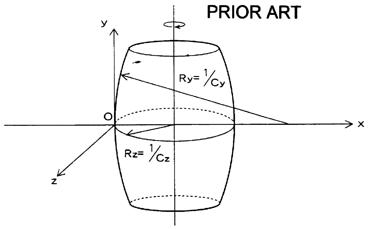
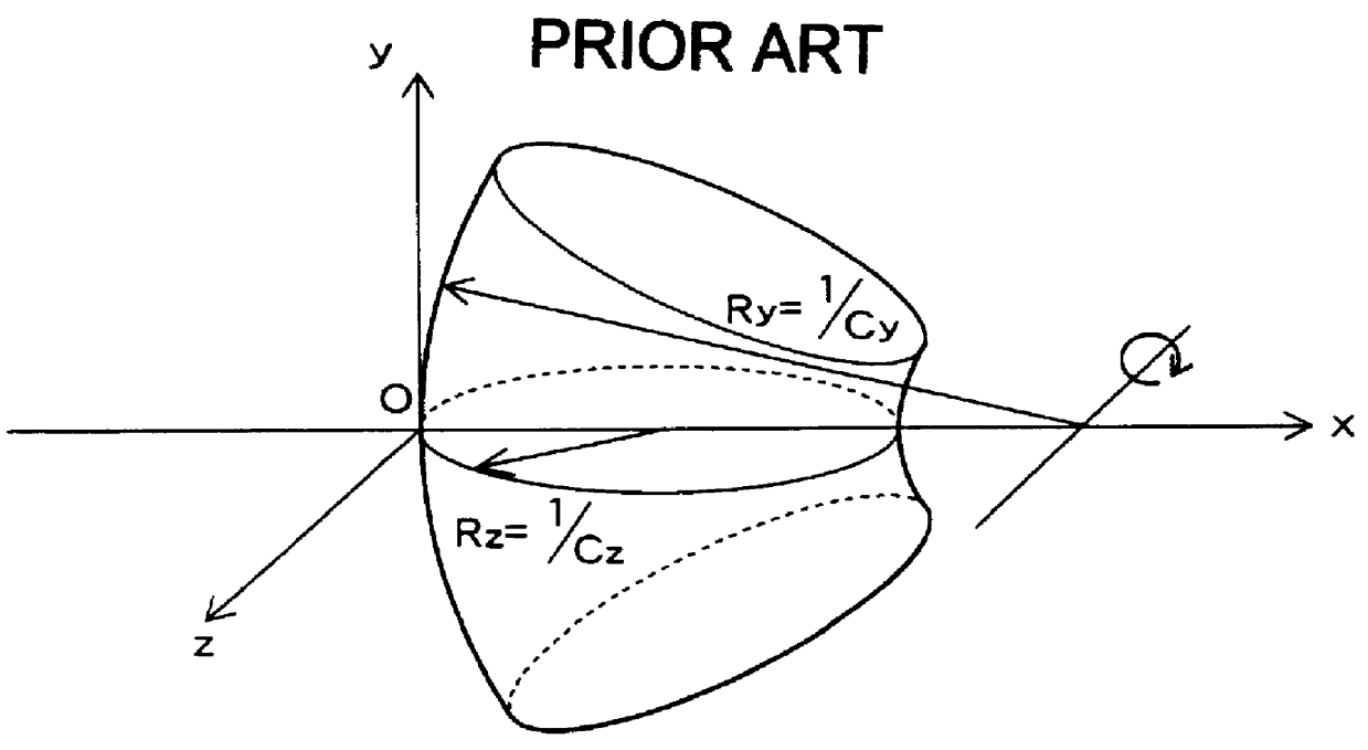
According to the conventional technique, the second surface is (a kind of) a toric surface. Namely, this curved surface is obtained by rotating a circular curve in the x-z plane, which is given by: ##EQU14## around a straight line which serves as an axis of rotation and is given by:

x=1 / C.sub.y and y=0.

In this case, C.sub.y


PUM


Abstract

An aspherical lens by which residual aberration in all of third eye-positions is corrected and which the center or edge thickness can be reduced. Thus, this aspherical lens employs a first or second curved surface represented by the following equation: where (x, y, z) represents the coordinates of a point on an aspherical surface and satisfies (y epsilon [a, b]) &andg& (z epsilon [c. d]); my is an order of a spline function in the direction of the y-axis (in this case, an integer which is not less than 4); mz is an order of the spline function in the direction of the z-axis (in this case, an integer which is not less than 4); ny is the number of inner knots in [a, b] in the direction of the y-axis (in this case, an integer which is not less than 4); nz is the number of inner knots in [c, d] in the direction of the z-axis (in this case, an integer which is not less than 4); Nmy,i (y) represents an ith my-th-order normalized B-spline function in the case that knots in the direction of the y-axis are xi 0, xi 1, xi 2, . . . , xi ny+2my-1 (incidentally, "i" is an integer within [o, nm+my-1] and the position of each knot meets the following condition: xi 0</= xi 1</=. . . </= xi my-1</=a< xi my</=. . . </= xi ny+my-1<b</= xi ny+my</=. . . </= xi ny+my+1; Nmz,i (z) represents an jth mz-th-order normalized B-spline function in the case that knots in the direction of the z-axis are xi 0, xi 1, xi 2, . . . , xi nz+2mz-1 (incidentally, "j" is an integer within [0, nz+mz-1] and the position of each knot meets the following condition: xi 0</= xi 1</=. . . </= xi mz-1</=c< xi mz</=. . . </= xi nz+mz-1<d</= xi nz+mz</=. . . </= xi nz+2mx-1; and ci,j is a coefficient.

Description

1. Field of the InventionThe present invention generally relates to a spectacle (or eyeglass) lens having a pair of first and second refractive (or refracting) surfaces (hereunder sometimes referred to simply as first and second surfaces, respectively), one or both of which have aspherical shapes. More particularly, the present invention relates to an astigmatic spectacle-lens (namely, a spectacle lens for correction of astigmatism).2. Description of the Related ArtIt is first supposed that the shape of a curved surface of a spectacle lens is represented by coordinates of a coordinate system shown in FIG. 1. Namely, it is supposed that an optical axis, thereof is set as the x-axis of the coordinate system shown in this figure and that the orientation (namely, the positive direction) of the optical axis (or x-axis) is the horizontally rightward direction thereof (as viewed in this figure). In this case, the eye of a spectacle lens wearer (namely, the wearer's line of sight) is direct...

Claims


Application Information

Patent Timeline
IPC IPC(8): G02C7/02
CPCG02C7/02
Inventor QI, HUA
Owner HOYA CORP
Why Eureka
Try Eureka