Safety utility belt

a safety and utility belt technology, applied in fishing, manufacturing tools, arm wearables, etc., can solve the problems of snagging, injury or death of workers, and the retaining rings on the utility belt can sometimes become snagged, so as to prevent snagging the retaining rings

Inactive Publication Date: 2000-01-18
WOJCIAK JEFFERY J +2
View PDF19 Cites 64 Cited by
  • Summary
  • Abstract
  • Description
  • Claims
  • Application Information

AI Technical Summary

Benefits of technology

It is thus an object of the invention to provide a safety utility belt that includes a number of retaining rings each provided with a safety cover flap securable over the retaining ring to prevent snagging of the retaining ring.
Accordingly, a safety utility belt is provided. The safety utility belt includes a heavy duty webbing back belt, a reflective center belt strip, a buckle assembly, a belt strip end that is coupleable to the buckle assembly to secure the back belt about the waist of a user, a horizontally pivoting tool retaining ring, a no-snag tool retaining ring safety cover flap securable over the tool retaining ring to prevent snagging of the tool retaining ring, a vertically pivoting attached D-ring, and a no-snag D-ring safety cover flap securable over the D-ring to prevent snagging of the D-ring; the no-snag tool retaining ring safety cover flap and the no-snag D-ring safety cover flap including a storage hook and pile fastener strip securable to a back side surface of the back belt when the no-snag tool retaining ring safety cover flap is folded backward against the back side of the back belt in a no-snag storage position.

Problems solved by technology

While in many jobs, such as firefighting and the like, it is desirable to attach tools of the trade, such as axes, flashlights, hammers, snips, etc, to a utility belt using a number of retaining rings, the retaining rings on the utility belt can sometimes become snagged while in the work environment and lead to injury or death for the worker.

Method used


Image

  • Safety utility belt
  • Safety utility belt

Examples


Embodiment Construction

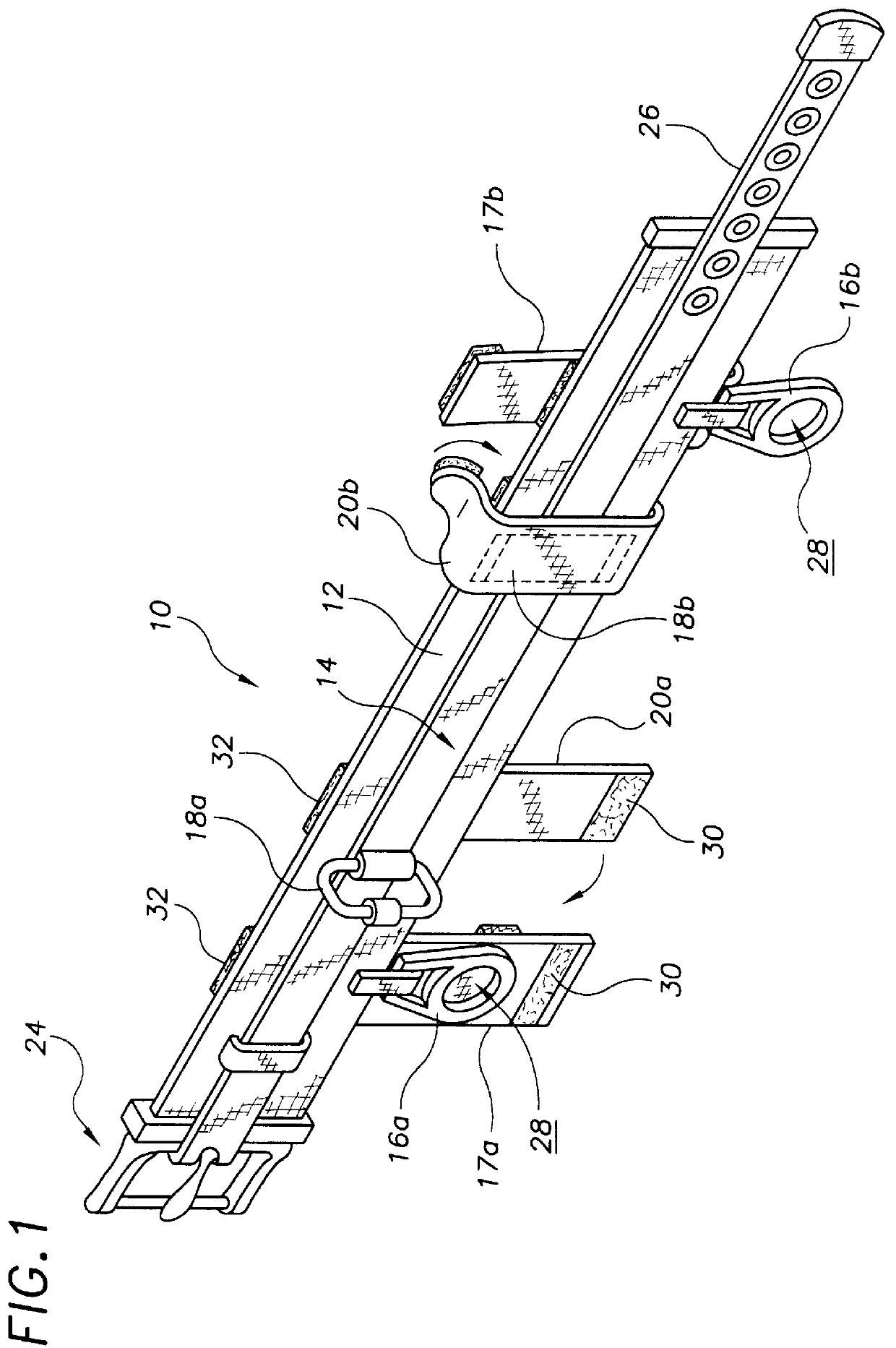
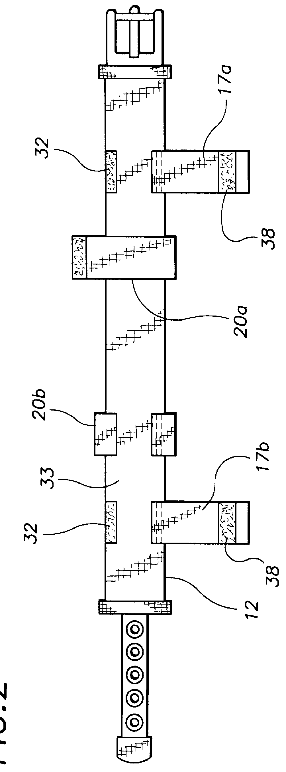
FIG. 1 shows an exemplary embodiment of the safety utility belt of the present invention generally designated by the numeral 10. Safety utility belt 10 includes a heavy duty nylon webbing back belt 12; the reflective coating coated, center belt strip, generally designated 14; two horizontally pivoting tool retaining rings 16a,16b; two no-snag tool retaining ring safety cover flaps 17a,17b; two identical vertically pivoting attached D-rings 18a,18b (18b shown in dashed lines); and two no-snag D-ring cover flaps 20a,20b.

Center belt strip 14 includes a conventional buckle assembly generally designated 24, a belt strap end 26, that is coupleable to buckle assembly 24 to secure back belt 12 about the waist of a user. In this embodiment reflective coating is an aluminized coating material.

The two horizontally pivoting tool retaining rings 16a,16b are each constructed from stainless steel and have a circular tool receiving opening 28 through which a portion of a tool such as a flashlight, ...


PUM


Abstract

A safety utility belt that includes a number of retaining rings each provided with a safety cover flap securable over the retaining ring to prevent snagging of the retaining ring. The safety utility belt includes a heavy duty webbing back belt, a reflective center belt strip, a buckle assembly, a belt strip end that is coupleable to the buckle assembly to secure the back belt about the waist of a user, a horizontally pivoting tool retaining ring, a no-snag tool retaining ring safety cover flap securable over the tool retaining ring to prevent snagging of the tool retaining ring, a vertically pivoting attached D-ring, and a no-snag D-ring safety cover flap securable over the D-ring to prevent snagging of the D-ring. The no-snag tool retaining ring safety cover flap and the no-snag D-ring safety cover flap include a storage hook and pile fastener strip that is securable to a companionate section of hook and pile fastener material provided on a back side surface of the back belt when the no-snag tool retaining ring safety cover flap is folded backward against the back side of the back belt in a no-snag storage position.

Description

The present invention relates to utility belts for carrying tools and the like and more particularly to a safety utility belt that includes a number of attachment rings that are each provided with a safety cover flap securable over the attachment structure to minimize dangerous snagging of the utility belt when working in confined areas or when in an emergency situation such as while performing firefighting activities; the safety utility belt including a heavy duty webbing back belt, a reflective center belt strip, a buckle assembly, a belt strip end that is coupleable to the buckle assembly to secure the back belt about the waist of a user, a horizontally pivoting tool retaining ring, a no-snag tool retaining ring safety cover flap securable over the tool retaining ring to prevent snagging of the tool retaining ring, a vertically pivoting attached D-ring, and a no-snag D-ring safety cover flap securable over the D-ring to prevent snagging of the D-ring; the no-snag tool retaining r...

Claims


Application Information

Patent Timeline
Patent Type & Authority Patents(United States)
IPC IPC(8): A45F5/02A45F5/00A41F9/00B25H3/00
CPCA41F9/002A45F5/02B25H3/00A45F5/00A45F2003/144A45F2200/0575Y10S224/904
Inventor WOJCIAK, JEFFERY J.LIS, DAVIDLANDINGHAM, TIMOTHY
Owner WOJCIAK JEFFERY J
Why Eureka
Try Eureka