

Extruded rail-mount with support leg
- Summary
- Abstract
- Description
- Claims
- Application Information
AI Technical Summary
Benefits of technology
Problems solved by technology
Method used
Image

Examples
an embodiment
B. Mounting an Embodiment
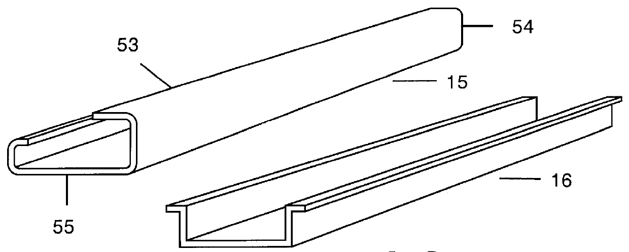
FIG. 5 shows the embodiment of FIG. 4 mounted to prior art `G` rail (15), plan view. The `G` rail is fixedly attached to surface 28. The rail provides the left side support, and support leg 8 provides right side support against surface 28. My substrate (22) bends slightly latitudinally upward by leg 8. This bending provides for an extra firm grip to a to-be-mounted circuit board. This bending keeps the board in place latitudinally, transversely, and longitudinally.
FIG. 6 is the embodiment of FIG. 4 mounted to prior art `wide-hat` rail (16). My Extruded Rail-Mount is mounted with a prior art circuit board 19 with screw terminals 20 and 21, plan view. The `wide-hat` rail is fixedly attached to surface 38. Again, the rail provides the left side support and support leg 8, resting on surface 38, provides right side support, and substrate 22 bends slightly latitudinally upward by leg 8. The arrangement provides plenty of support for screwing to terminals 20 and 21...
PUM
 Abstract
Description
Claims
Application Information