Elastomer damping of pivoted pinch roll

a technology of elastomer and roller, which is applied in the direction of transportation and packaging, thin material processing, and article separation, etc., can solve the problems of overheating of the roller, interfering with the normal functioning of the (movable) roller,

Inactive Publication Date: 2000-02-01
BURROUGHS CORP
View PDF9 Cites 11 Cited by
  • Summary
  • Abstract
  • Description
  • Claims
  • Application Information

AI Technical Summary

Problems solved by technology

These gaps collect paper dust which can interfere with normal functioning of the (movable) pinch roller.
But this can cause overheating in the roller due to its constant rotation with a pinch load.

Method used


Image

  • Elastomer damping of pivoted pinch roll
  • Elastomer damping of pivoted pinch roll
  • Elastomer damping of pivoted pinch roll

Examples


Embodiment Construction

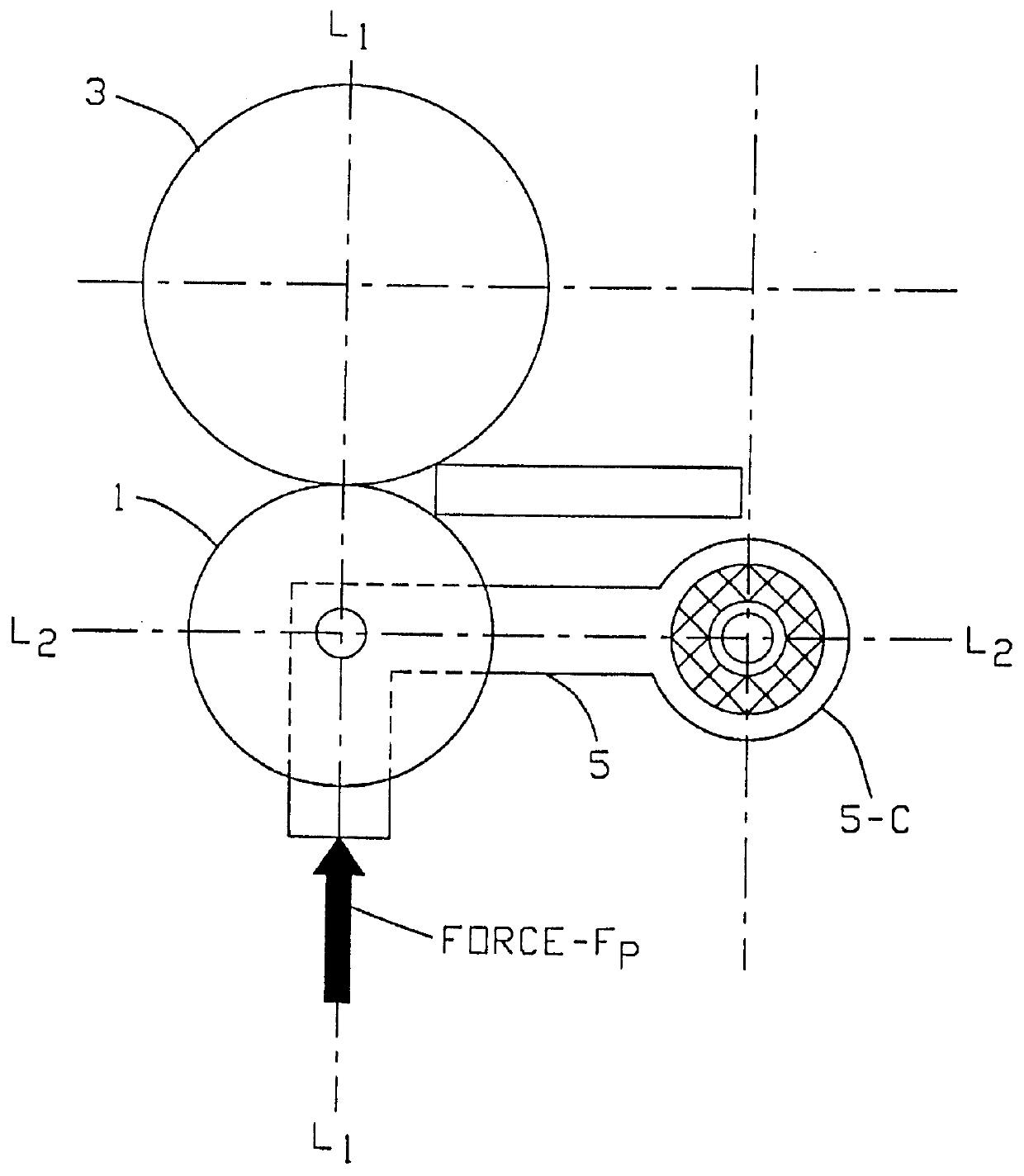
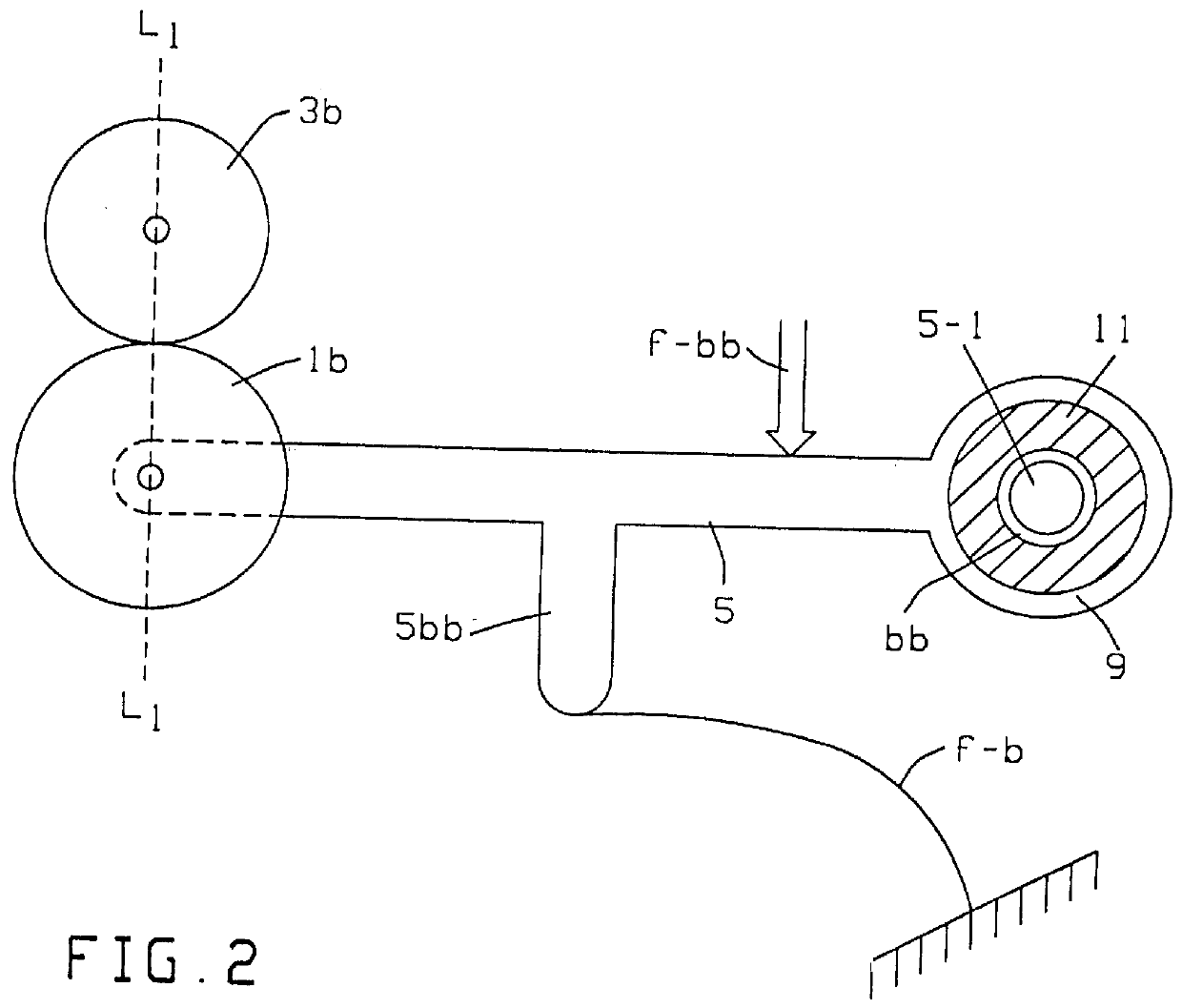
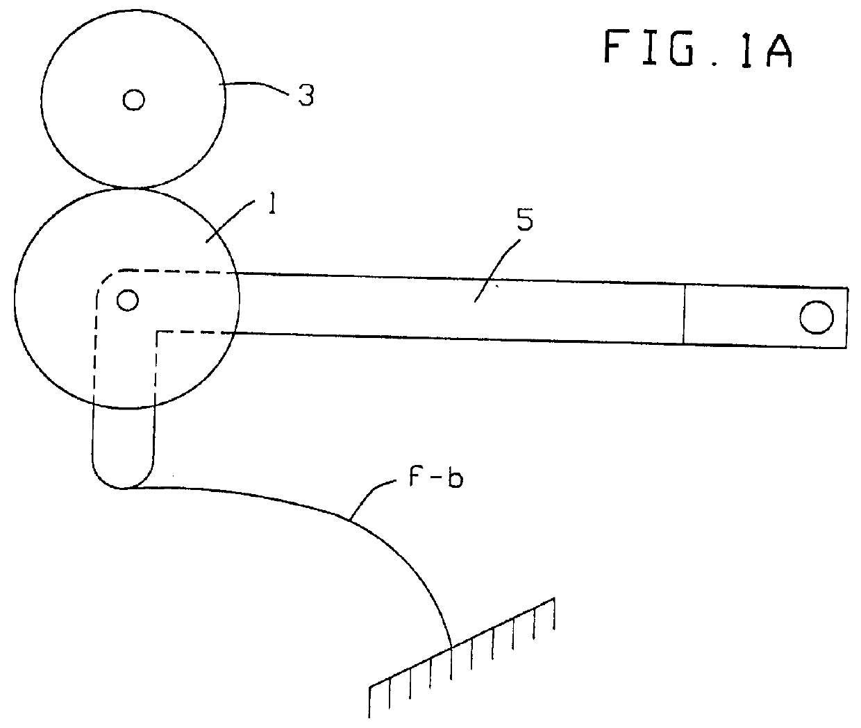
FIG. 1 depicts a moveable pinch roll 1 opposed by a fixed drive roll 3 which may be assumed as rotated about its center by any number of known contemporary means. Normally, a document D is moved to the nip between this roll pair by known document feed means (eg. another upstream roll assembly, not shown--e.g. in a high-speed check-sorter). And the document will be withdrawn from this roll assembly 1,3 to output means, such as another roll pair or to a stacker (neither shown, but well known in the art).

Moving Pinch roll 1, is cantilevered-out on an arm 5 which is free to pivot about a fixed end (eg. on a shaft 7, usually with sealed ball bearings to minimize friction and to prevent paper dust from accumulating in the bearing.

This fixed end of arm 5 comprises a flexible pivot assembly including a rigid hollow outer cylinder-end, 5-C enclosing a resilient damping cylinder (tube or sleeve 11) which, in turn, surrounds a rigid hollow inner cylinder 9 mounted to rotate on fixed shaft 7. D...


PUM


Abstract

A document feed array comprising a pinch-roll mounted to rotate about its center to engage documents, being mounted on a cantilever-arm pivoted at a point distal from the roll-center and including an elastomeric sleeve which, alone, couples the arm to its pivot point (in operation), the sleeve comprising high-damping, durable elastomeric material adapted to accommodate thickness anomalies in the documents, yet to maximize driving contact therewith.

Description

This invention relates to document transport equipment, and especially to pinch rolls therefor.BACKGROUND FEATURESWorkers are aware that new and innovative high speed document transport systems are desirable. Workers are active in this field. Examples are described in U.S. Pat. Nos. 5,029,845, 4,974,680, 5,098,082, 5,172,900, 4,903,954, 4,346,883, 4,425,694. Many such systems have typically employed opposed pinch-rolls and to accommodate variance in document thickness etc., have used silient means therewith.Previous resilient elements, such as air dashpots, bushings, sliding contact devices, and magnetic devices, require small gaps between components. These gaps collect paper dust which can interfere with normal functioning of the (movable) pinch roller. Other devices employ flexible damping material in the pinch roll (roller) itself. But this can cause overheating in the roller due to its constant rotation with a pinch load.My invention avoids the foregoing problems, and involves m...

Claims


Application Information

Patent Timeline
Patent Type & Authority Patents(United States)
IPC IPC(8): B65H5/06
CPCB65H5/062B65H2402/31B65H2402/632B65H2701/1912B65H2402/60
Inventor TRANQUILLA, MICHAEL N.
Owner BURROUGHS CORP
Why Eureka
Try Eureka