Method of welding in the horizontal position and welding apparatus therefor

a horizontal position and welding apparatus technology, applied in the direction of soldering apparatus, manufacturing tools,auxillary welding devices, etc., can solve the problems of low efficiency, inability to easily invert structures, and insufficient fusion

Inactive Publication Date: 2000-02-08
MITSUBISHI HEAVY IND LTD
View PDF9 Cites 52 Cited by
  • Summary
  • Abstract
  • Description
  • Claims
  • Application Information

AI Technical Summary

Problems solved by technology

Because such large structures cannot easily be inverted during production, some portions must be welded in the horizontal position.
This may lead to welding defects such as inadequate fusion when the subsequent layer is welded.
And since such mechanisms are still not enough, the process must be co...

Method used


Image

  • Method of welding in the horizontal position and welding apparatus therefor
  • Method of welding in the horizontal position and welding apparatus therefor
  • Method of welding in the horizontal position and welding apparatus therefor

Examples


Embodiment Construction

The object of the present invention is to provide a method of welding in the horizontal position which is highly efficient and which prevents the occurrence of defective welds caused by undercuts or overlaps, and to provide a welding apparatus to execute this method.

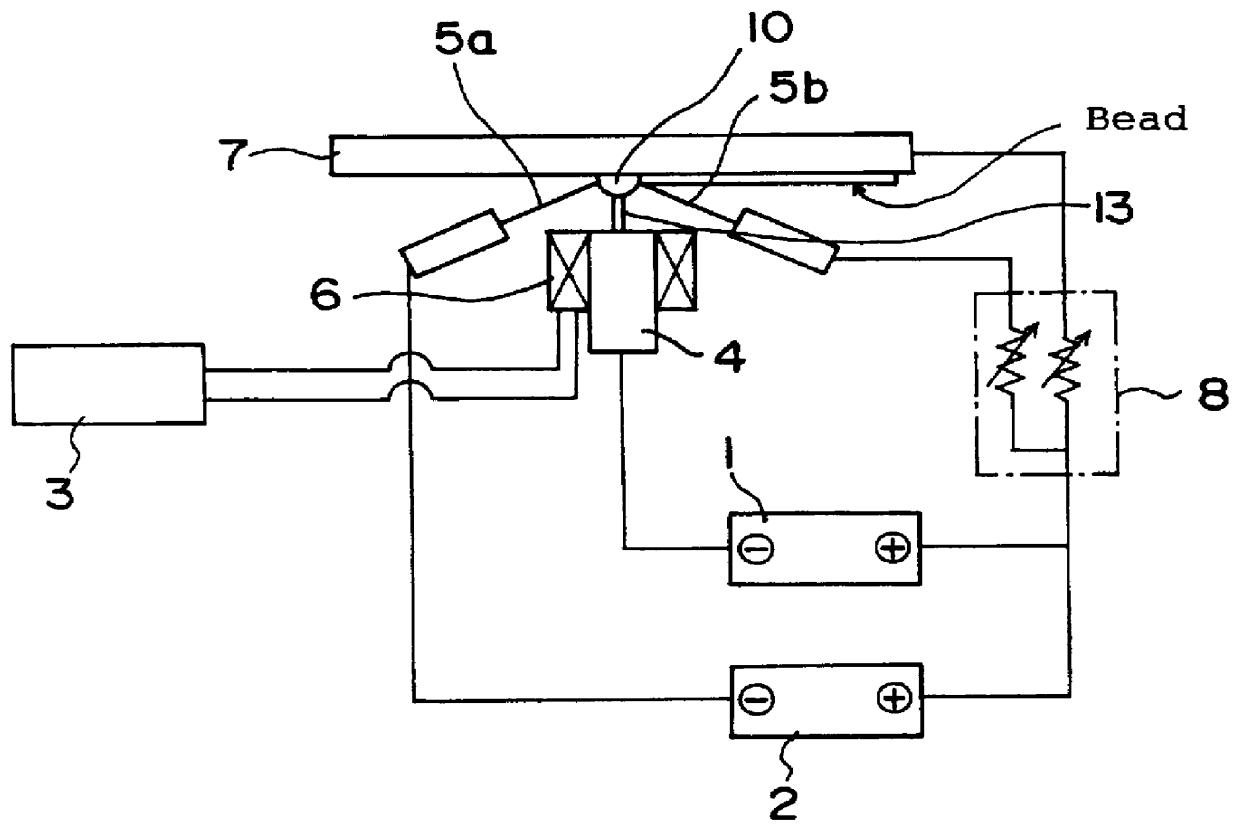
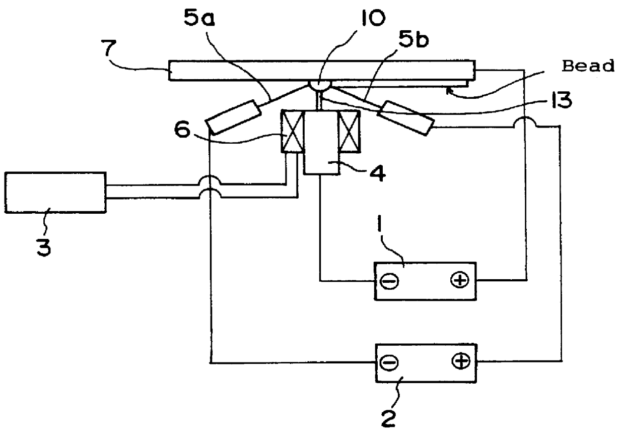
In order to solve the problems outlined above, the present invention is designed as follows. It concerns a method of welding in the horizontal position, in which a heat source such as an arc, a laser or an electron beam is used to melt the parent material and form a molten pool. Because of the position of the weld, gravity tends to cause the bead to deform.

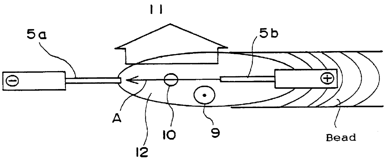
This welding method is distinguished by the following. A current is made to flow in the molten pool in approximately the same direction as the weld line, and a magnetic field is induced in the molten pool orthogonal to the direction of the current. The joint is welded while an upward Lorentz force (opposite the direction of gravity) is generated in the molten pool.

The ...


PUM

PropertyMeasurementUnit
Forceaaaaaaaaaa
Flow rateaaaaaaaaaa
Magnetic fieldaaaaaaaaaa

Abstract

PCT No. PCT/JP97/01533 Sec. 371 Date Jan. 12, 1998 Sec. 102(e) Date Jan. 12, 1998 PCT Filed May 7, 1997 PCT Pub. No. WO97/43073 PCT Pub. Date Nov. 20, 1997The object of this invention is to prevent the occurrence of welding defects such as undercuts, overlaps and faulty angles of fusion, and to increase the efficiency of welding in the horizontal position. Auxiliary wires 5a and 5b are inserted into molten pool 12, and a unidirectional current is made to flow between them. A magnetic field 9 is induced which is approximately orthogonal to the surface of the parent material so as to generate an upward Lorentz force (opposite the pull of gravity) in molten pool 12. This force supports the molten metal and prevents it from dripping, resulting in a better-shaped bead.

Description

This invention concerns a method of welding in the horizontal position, in which the molten pool is liable to experience deformation under the influence of gravity, and a welding apparatus for that purpose. More specifically, it concerns a welding method in the horizontal position to be used in the production of large structures such as smokestacks, bridges, pressure vessels and the like, and a welding apparatus for that purpose.BACKGROUND OF THE TECHNOLOGYWelding has been an indispensable process in the manufacture of large steel structures such as smokestacks, bridges and pressure vessels. Because such large structures cannot easily be inverted during production, some portions must be welded in the horizontal position.In butt welding, four welding positions may be used: the flat position, the horizontal position, the vertical position and the overhead position. In fillet welding, four welding positions also may be used: the flat position, the horizontal position, the vertical posi...

Claims


Application Information

Patent Timeline
IPC IPC(8): B23K26/00B23K26/14B23K37/06B23K26/24B23K9/167B23K9/08B23K9/173B23K26/21
CPCB23K9/08B23K9/167B23K9/1675B23K9/1735B23K15/0046B23K26/1423B23K26/24B23K37/06B23K26/1429B23K26/348
Inventor MANABE, YUKIOZENITANI, SATORUHIROMOTO, YOSHINORI
Owner MITSUBISHI HEAVY IND LTD
Why Eureka
Try Eureka