Lens antenna with tapered horn and dielectric lens in horn aperture

a dielectric lens and lens technology, applied in the field of lenses, can solve the problems of degrading the radiation pattern and antenna efficiency, wave absorber, and antenna efficiency degradation

Inactive Publication Date: 2000-02-08
NEC CORP
View PDF9 Cites 41 Cited by
  • Summary
  • Abstract
  • Description
  • Claims
  • Application Information

AI Technical Summary

Problems solved by technology

The first problem of the conventional lens antenna lies in the fact that the reflections of high-frequency signals on the lens surface degrade the radiation pattern and antenna efficiency.
This is because reflections of high-frequency signals on the lens surface repeat multiple reflections between a surface of the lens and the inner wall of the horn to disturb the power distribution of the high-frequency at the aperture of the lens.
The second problem lies in the fact that, when the wave absorber to the inner wall of the horn is bonded to reduce the sidelobe level of the radiation pattern, high-frequency signals are screened by the wave absorber and antenna efficiency is degraded.
The third problem lies in the fact that the bonding of the wave absorber onto the curved surface of the inner wall of the horn with an adhesive is difficult and reduces productivity.

Method used


Image

  • Lens antenna with tapered horn and dielectric lens in horn aperture
  • Lens antenna with tapered horn and dielectric lens in horn aperture
  • Lens antenna with tapered horn and dielectric lens in horn aperture

Examples


Embodiment Construction

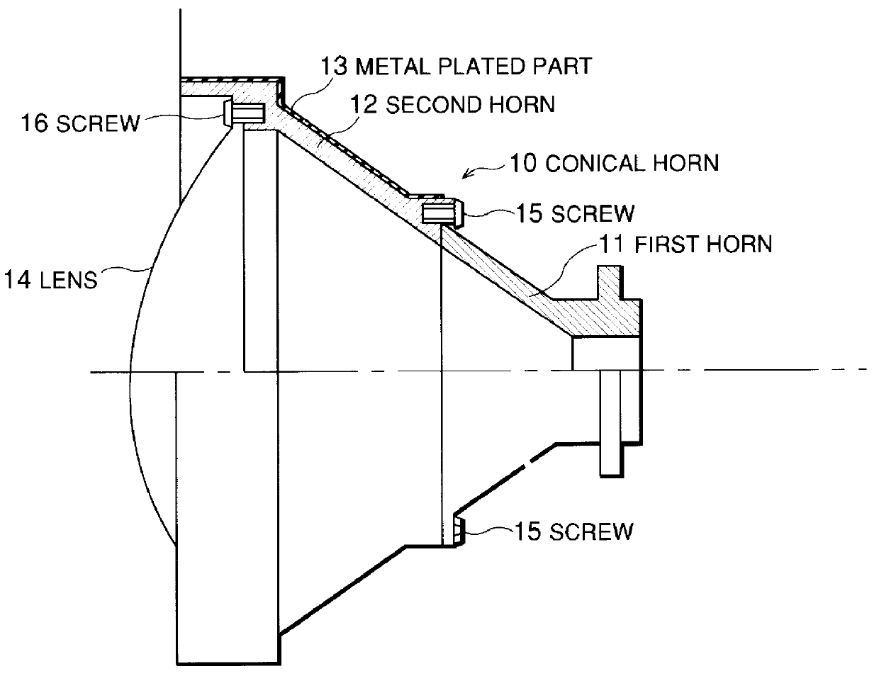
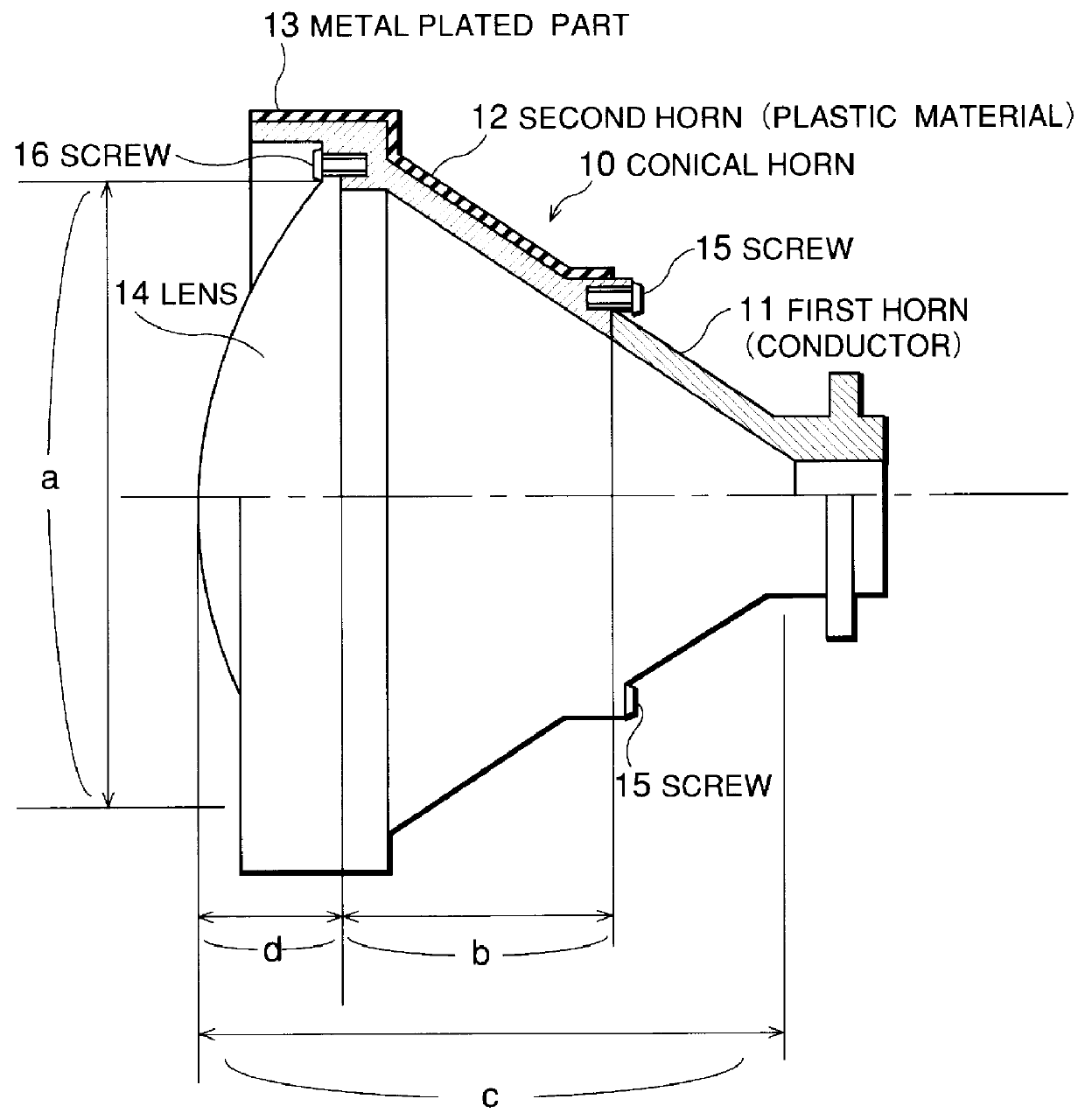
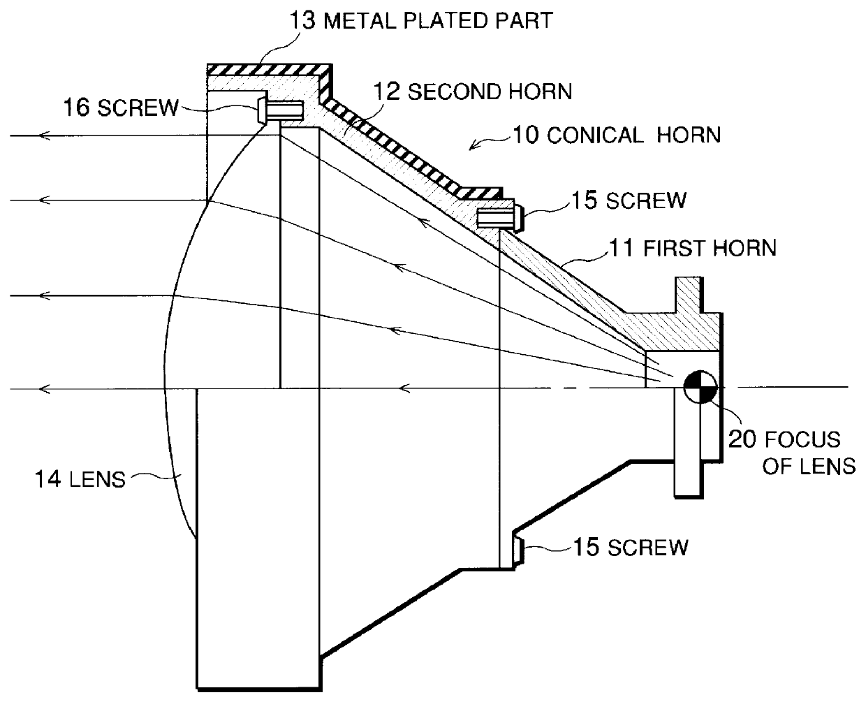
With reference now to FIG. 1, the lens antenna of the first embodiment of the present invention comprises a conical horn 10 that includes a first horn 11 having a circular waveguide made of a metallic conductor and a second horn 12 having a high-frequency absorbing function, a circular lens 14 for controlling the power distribution at the aperture of the second horn 12, and screws 15 and 16 for assembling the first horn 11, the second horn 12, and the lens 14.

The first horn 11 is desirably conical, and one end forms a circular waveguide for inputting high-frequency signals. The other end of first horn 11 has a flange structure for connecting the second horn 12. First horn 11 may be made of aluminum. The second horn 12 forms an extension of the first horn 11, and has one flanged end for connecting the first horn 11 and a second flanged end for connecting the lens 14. Second horn 12 may be made of a plastic material formed by adding a proper amount of carbon to polycarbonate resin and...


PUM


Abstract

A lens antenna having high antenna efficiency, low sidelobe levels, and that is easily assembled. The lens antenna includes a first horn made of a metallic conductor, a second horn made of a high-frequency absorbing plastic material, and a lens for controlling the power distribution at an aperature of the horn. Screws may be used to assemble the first horn, the second horn, and the lens. Though some of the microwave signals input through the circular waveguide of the first horn are reflected on the surface of the lens, most of the microwave signals are absorbed by the second horn. Moreover, because no wave absorber is bonded to an inner wall of a conical horn, nothing screens the microwave signal, the power density distribution at the aperture of the lens is not disrupted. Therefore, it is possible to obtain a desired power density distribution.

Description

1. Field of the InventionThe present invention relates to a lens antenna, particularly to the lens antenna for transmitting / receiving microwave band signals or millimeter-wave band signals and to a method of controlling sidelobe levels.2. Description of the Related ArtIn a conventional lens antenna, a dielectric circular lens is set in an aperture of a horn antenna for the microwave band signals or the millimeter-wave band signals to improve antenna efficiency as disclosed in the official gazette of Japanese Patent Laid-Open No. 219802 / 1983.In FIG. 6, symbol 30 denotes a conical horn, 34 denotes a lens, 36 denotes a screw, and 37 denotes a wave absorber. The dielectric lens 34 is circular and is set in the aperture of the metallic conical horn 30. Moreover, in this conventional lens antenna, the wave absorber 37 is bonded to an inner wall of the conical horn 30 with an adhesive to reduce the sidelobe level of the radiation pattern of the lens antenna.The first problem of the convent...

Claims


Application Information

Patent Timeline
Patent Type & Authority Patents(United States)
IPC IPC(8): H01Q19/08H01Q19/00H01Q13/02H01Q19/06H01Q17/00H01Q19/09
CPCH01Q19/08
Inventor TANABE, KOSUKE
Owner NEC CORP
Why Eureka
Try Eureka