Reciprocating pistons of piston-type compressor

a piston-type compressor and piston-type technology, applied in the direction of machines/engines, mechanical equipment, positive displacement liquid engines, etc., can solve the problems of increasing the overall weight of the piston, increasing the production cost of the piston, and reducing the efficiency of the compressor

Inactive Publication Date: 2000-02-15
SANDEN CORP
View PDF32 Cites 31 Cited by
  • Summary
  • Abstract
  • Description
  • Claims
  • Application Information

AI Technical Summary

Problems solved by technology

Accordingly, this configuration results in increasing the overall weight of piston 38 or in increa...

Method used


Image

  • Reciprocating pistons of piston-type compressor
  • Reciprocating pistons of piston-type compressor
  • Reciprocating pistons of piston-type compressor

Examples


Embodiment Construction

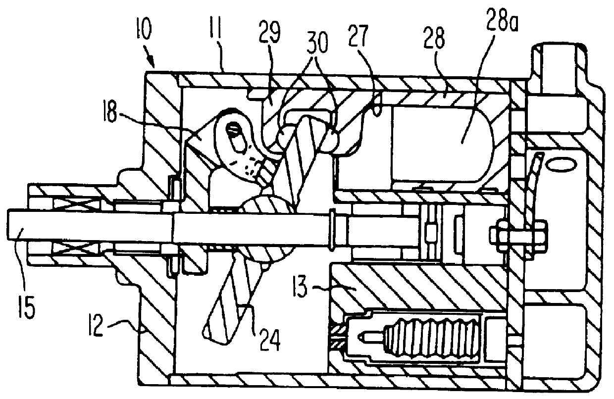
A piston-type compressor, in which fluid is compressed by means of reciprocating pistons connected to a swash plate is described in U.S. patent application Ser. No. 08 / 816,691, filed on Mar. 13, 1997, which is incorporated herein by reference. Referring to FIG. 5, a swash plate-type compressor is described as a reciprocating compressor according to a first embodiment of the this invention. In the following description, the left side of FIG. 5 will be referred to as front side of the compressor while the right side thereof will be referred to as the rear side of the compressor. These labels are only for the sake of convenience of description and are not intended to limit the invention in any way.

The swash plate-type compressor of FIGS. 5-7 is for use in a vehicle air conditioner and is generally called a single head piston-type. Referring to FIGS. 5-7, in the swash plate-type compressor, a cylinder block 101 is formed therein with seven bores 101a arranged circumferentially in parall...


PUM

PropertyMeasurementUnit
Angleaaaaaaaaaa
Efficiencyaaaaaaaaaa

Abstract

A piston-type compressor has seven cylinder bores formed in a cylinder block which is formed in a compressor housing. A piston is slidably disposed within each of the cylinder bores. Each of the pistons includes a cylindrical main body and an engaging portion axially extending from the cylindrical body. A drive shaft is rotatably supported in the cylinder block. A bearing couples the plate to each of the pistons, so that the pistons reciprocate within the cylinder bores upon rotation of the plate which is tiltably connected to the drive shaft. A recessed portion is formed in an interior of the cylindrical body of each piston so that the cylindrical body forms a C-shaped cross-section perpendicular to longitudinal axis of the piston. Therefore, the configuration obtains lightweight pistons while simultaneously maintaining the efficiency of the compressor.

Description

1. Field of the InventionThe present invention relates to a piston-type compressor, in which fluid is compressed by means of reciprocating pistons connected to a swash plate. More particularly, it relates to a configuration of reciprocating pistons, which reduces the weight of the pistons in the refrigerant compressor for an automotive air conditioning system.2. Description of the Related ArtA variable capacity, swash plate-type compressor is disclosed in U.S. Pat. No. 4,664,604, which is incorporated herein by reference. Referring to FIG. 1, a cylinder block 13 is accommodated in cylinder housing 11 of a compressor 10. Pistons 28 are accommodated in cylinder bores 27 and are reciprocatedly moved therein. A drive shaft 15, which is driven by an engine (not shown), is rotatably supported by means of the central portion of cylinder block 13 and a front cover 22. Rotor plate 18 is mounted on drive shaft 15, and synchronously rotates with draft shaft 15. Further, a swash plate 24 is til...

Claims


Application Information

Patent Timeline
IPC IPC(8): F01B3/00F04B27/08F04B39/00
CPCF01B3/0002F04B27/0878F05C2225/04
Inventor MORITA, YUJIRO
Owner SANDEN CORP
Why Eureka
Try Eureka