Front suspension of motor vehicle

Inactive Publication Date: 2000-02-22
NISSAN MOTOR CO LTD
View PDF9 Cites 50 Cited by
  • Summary
  • Abstract
  • Description
  • Claims
  • Application Information

AI Technical Summary

Problems solved by technology

However, this arrangement tends to bring about the following undesired phenomena.
However, in this case, the rearward shifting of the wheel center upon bounding is not achieved and thus the ride quality becomes poor.
These necessities tend to narrow the freedom in designing the layout of parts of the vehicle body, particularly, the layout of the parts in the engine room.
Furthermore, if the shock absorber is arranged to be largely inclined, reduction of the lever ratio tends to occur and the friction resistance generated by the shock absorbe

Method used


Image

  • Front suspension of motor vehicle
  • Front suspension of motor vehicle
  • Front suspension of motor vehicle

Examples


Example

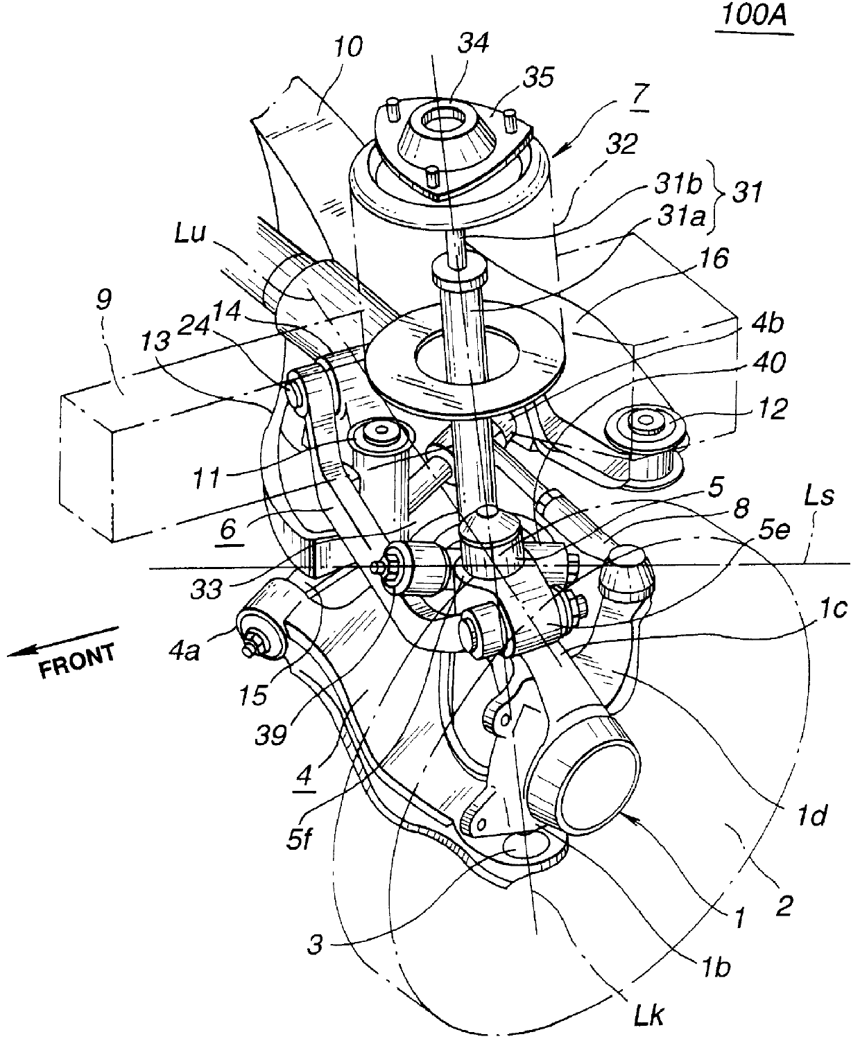
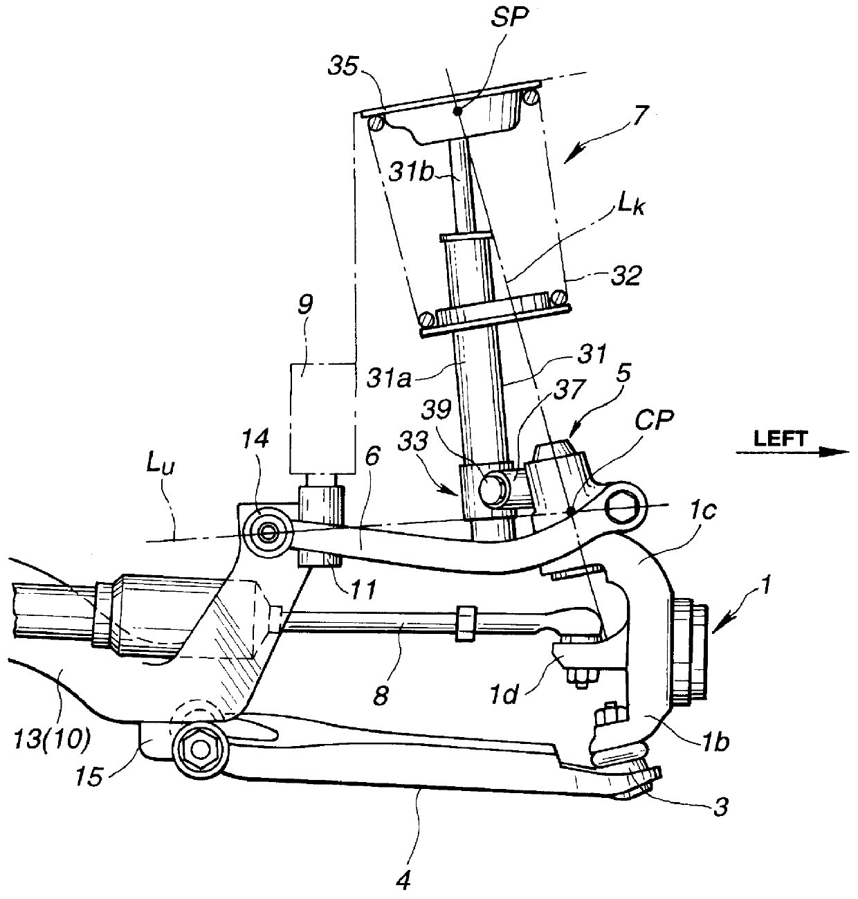
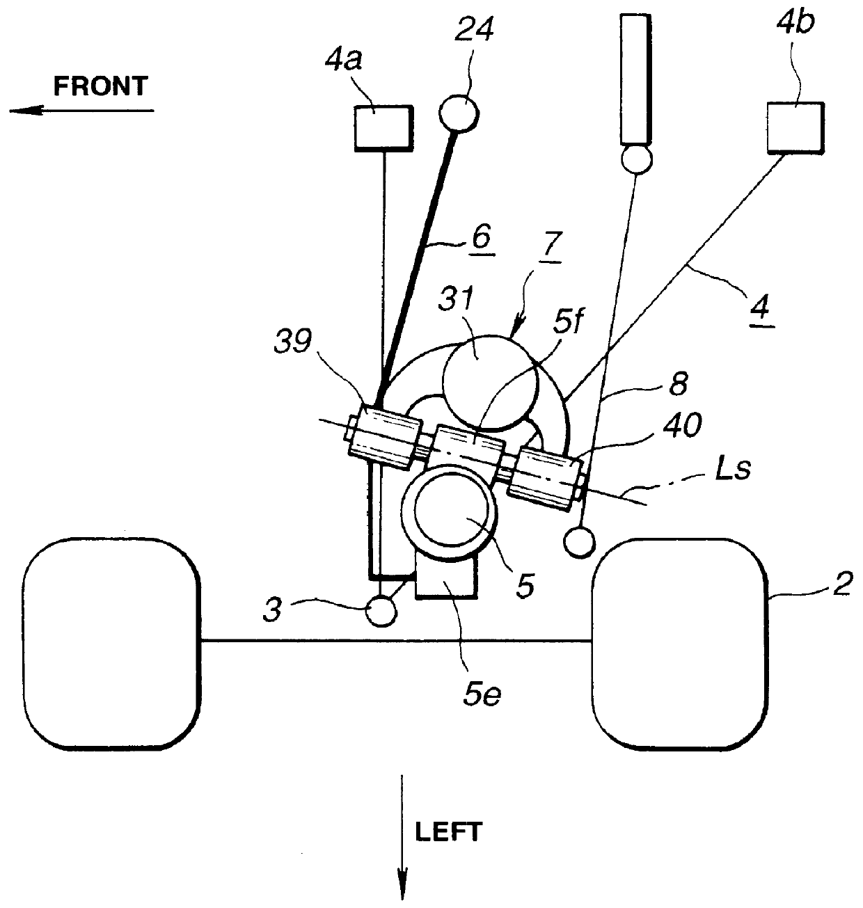
Referring to FIGS. 1 and 2, particularly FIG. 1, there is shown a front suspension 100A which is a first embodiment of the present invention.

In the drawings, denoted by numeral 1 is a steering knuckle (or wheel supporting member) which rotatably supports a front wheel 2. The steering knuckle 1 has at a center portion thereof a cylindrical bore 1a through which an axle of the front wheel 2 passes. To a lower portion 1b of the steering knuckle 1, there is connected a lower link 4 through a ball-joint 3. To an upper portion 1c of the steering knuckle 1, there are connected through a rotatable connecting member 5 both an upper link 6 and a strut 7. To a supporting portion 1d which projects rearward from a center portion of the knuckle 1, there is connected a tie rod 8 which is connected to a steering device (not shown).

A side member 9 extends in a longitudinal direction of the vehicle inside the steering knuckle 1. To a lower surface of the side member 9, there is connected through resi...

Example

Alternatively, if desired, as is shown in FIGS. 14 and 15 which shows a front suspension of a second embodiment 100B of the present invention, the lower link 4 may comprise two I-shaped lower link parts, each having an outside end connected to the lower portion of the steering knuckle 1 through a ball-joint 3A or 3B and the other end supported to the vehicle body side member at a point 4a or 4b. In that case, an intersection line between a first imaginary plane PS1 which contains the point 4a, a center of the ball-joint 3A and the body connecting point "SP" and a second imaginary plane PS2 which contains the point 4b, a center of the ball-joint 3B and the body connecting point "SP" forms a virtual king pin axis "L.sub.K' " which does not pass through the ball-joints 3A and 3B. That is, in spite of interference with the other parts such as a brake rotor, the king pin axis "L.sub.K' " can be set in the most suitable position.

The contents of Japanese Patent Application 9-300588 filed O...


PUM


Abstract

A steering knuckle has an upper portion and a lower portion. A lower link has an outside end rotatably connected to the lower portion of the steering knuckle and an inside end swingably supported by a vehicle body. A connecting member is rotatably mounted to the upper portion of the steering knuckle. A first axis (Lk) is defined about which the connecting member rotates relative to the upper portion of the steering knuckle. A shock absorber has an upper end pivotally connected to the vehicle body and a lower end connected to the connecting member. An upper link has an inside end pivotally connected to the vehicle body and an outside end pivotally connected to the connecting member. A second axis (Lu) is defined which passes through both the pivoted inside end of the upper link and the pivoted outside end of the same. A tie rod is connected to the steering knuckle to pivot the same about the first axis. The lower link and the upper link are arranged to exhibit a negative camber characteristics upon bounding, and the shock absorber is supported by the connecting member in a manner to pivot about a third axis (Ls). The third axis (Ls) is inclined with respect to a longitudinal axis of the vehicle in such a manner that a lateral distance of the third axis from the longitudinal axis increases as the third axis extends rearward.

Description

1. Field of the InventionThe present invention relates in general to suspensions of wheels of motor vehicles, and more particularly to front suspensions for front wheels of the motor vehicles.2. Description of the Prior ArtFor clarifying the task of the invention, one known front suspension will be described, which is disclosed in Japanese First Provisional Publication 5-178041.In the known front suspension, a lower end of a steering knuckle is connected through two lower links to the vehicle body in such a manner that the steering knuckle can swing up and down. A connecting member is connected to an upper portion of the steering knuckle in such a manner as to pivot horizontally, that is, to rotate about a vertical axis. The connecting member is connected to a lower end of a shock absorber so that the connecting member can swing up and down together with the steering knuckle. An inside end of an upper link is pivotally connected to the vehicle body. An outside end of the upper link ...

Claims


Application Information

Patent Timeline
IPC IPC(8): B60G15/07B60G15/00B60G3/26B60G3/18B60G3/20
CPCB60G3/265B60G15/07B60G2200/144B60G2200/156B60G2200/44B60G2200/46B60G2200/462B60G2204/129B60G2204/148B60G2204/416B60G2204/418B60G2204/422B60G2204/4304
Inventor KAWABE, YOSHIHIROKASAHARA, TAMIYOSHI
Owner NISSAN MOTOR CO LTD
Why Eureka
Try Eureka