Shock absorber

a technology of shock absorber and shock absorber, which is applied in the direction of shock absorbers, mechanical equipment, transportation and packaging, etc., can solve the problems of difficult to suppress vibrations over this frequency level, and the vibration frequency significantly affecting the ride quality of the vehicle is higher, so as to improve the ride quality of the vehicle and improve the ride quality

Inactive Publication Date: 2016-08-11
KYB CORP
View PDF8 Cites 14 Cited by
  • Summary
  • Abstract
  • Description
  • Claims
  • Application Information

AI Technical Summary

Benefits of technology

[0008]However, a chassis vibration frequency significantly affecting the vehicle ride quality is higher than the aforementioned dampable frequency level. Such a high frequency vibration is not suppressed by the shock absorber described above. Therefore, it is desired to further improve the vehicle ride quality.
[0009]In view of the aforementioned problems, it is therefore an object of the present invention to provide a shock absorber capable of improving a vehicle ride quality.

Problems solved by technology

For this reason, it is difficult to suppress vibrations over this frequency level.
However, a chassis vibration frequency significantly affecting the vehicle ride quality is higher than the aforementioned dampable frequency level.

Method used


Image

  • Shock absorber
  • Shock absorber
  • Shock absorber

Examples


first embodiment

[0025]A description will now be made for a shock absorber 51 according to a first embodiment of the present invention with reference to the accompanying drawings.

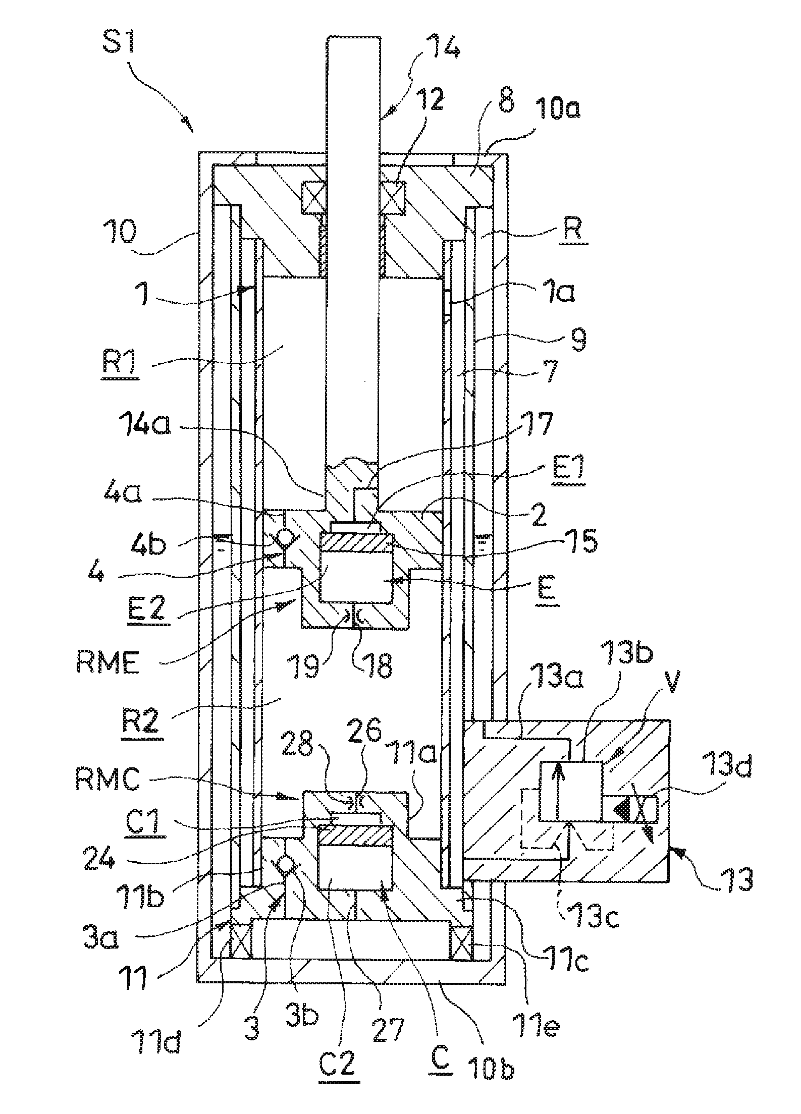
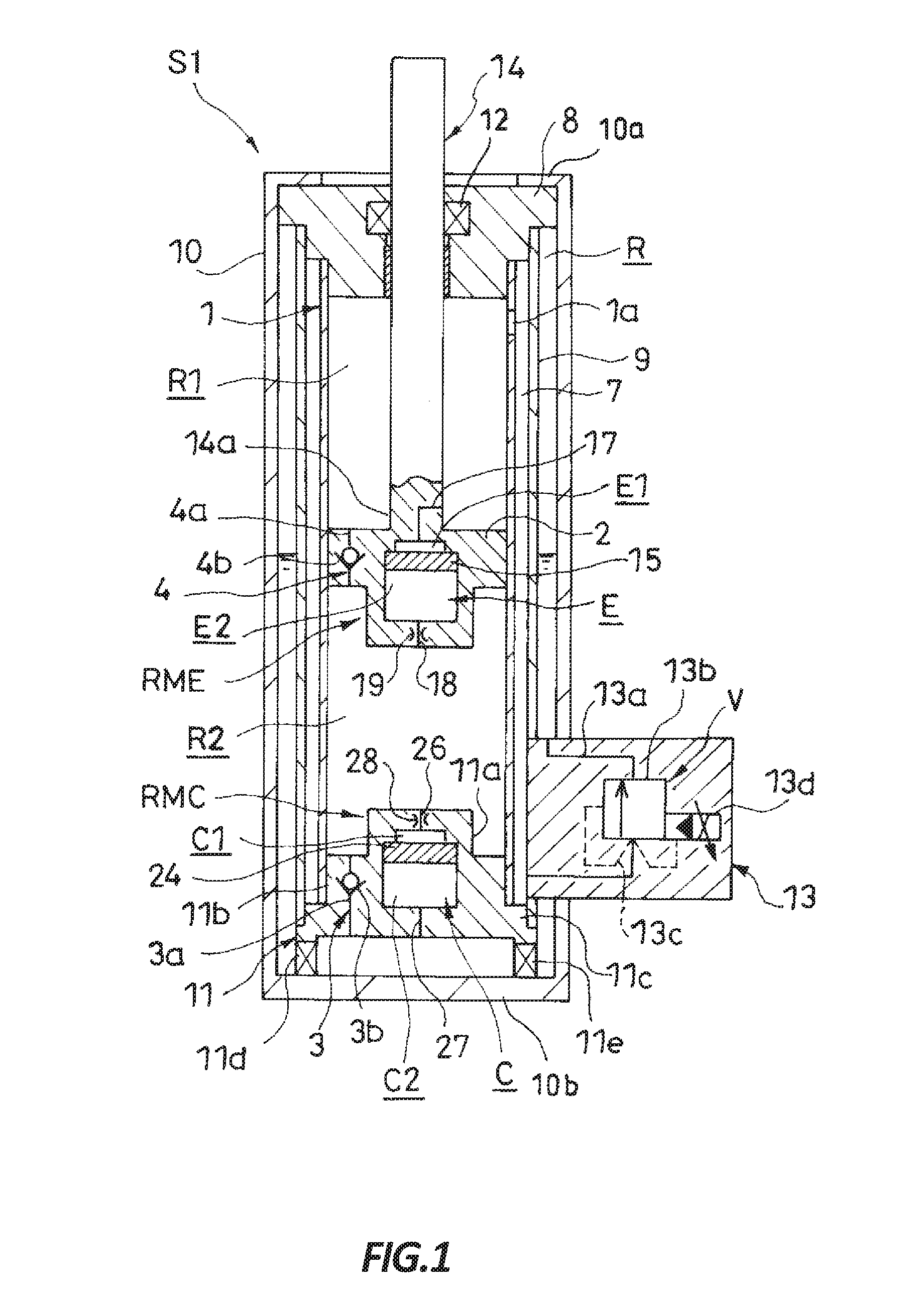
[0026]Referring to FIG. 1, the shock absorber 51 includes a cylinder 1, a piston 2 slidably inserted into the cylinder 1 to partition the cylinder 1 into an expansion-side chamber R1 and a contraction-side chamber R2, a piston rod 14 movably inserted into the cylinder 1 and connected to the piston 2, a reservoir R that stores hydraulic oil as hydraulic fluid, a charge passage 3 that allows only a flow of hydraulic oil directed from the reservoir R to the contraction-side chamber R2, a rectification passage 4 that allows only a flow of hydraulic oil directed from the contraction-side chamber R2 to the expansion-side chamber R1, and a damping force variable valve V as a damping force adjuster that allows only a flow of hydraulic oil directed from the expansion-side chamber R1 to the reservoir R and capable of changing resista...

second embodiment

[0111]Next, a description will now be made for a shock absorber S2 according to a second embodiment of the present invention.

[0112]Referring to FIG. 5, the shock absorber S2 is provided with a check valve 50 that allows only a flow of hydraulic oil directed from the contraction-side chamber R2 to the expansion-side chamber R1. The check valve 50 is arranged in parallel with the expansion-side valve element 19.

[0113]According to this embodiment, the expansion-side valve element 19 is provided in the second expansion-side passage 18. Therefore, the check valve 50 is preferably set to allow only a flow of hydraulic oil directed from the contraction-side chamber R2 to the second expansion-side pressure chamber E2 corresponding to a flow of hydraulic oil directed from the contraction-side chamber R2 to the expansion-side chamber R1.

[0114]As a result, when the shock absorber S2 makes an expanding motion so that the expansion-side free piston 15 moves to compress the second expansion-side ...


PUM


Abstract

A shock absorber includes at least one of an expansion-side sensitive unit and a contraction-side sensitive unit. The expansion-side sensitive unit has an expansion-side actuating chamber that communicates with an expansion-side chamber and a contraction-side chamber, and an expansion-side free piston that partitions the expansion-side actuating chamber into a first expansion-side pressure chamber and a second expansion-side pressure chamber. The contraction-side sensitive unit has a contraction-side actuating chamber that communicates with a contraction-side chamber and a reservoir, and a contraction-side free piston that partitions the contraction-side actuating chamber into a first contraction-side pressure chamber and a second contraction-side pressure chamber.

Description

TECHNICAL FIELD[0001]The present invention relates to a shock absorber.BACKGROUND ART[0002]There is known a damping force adjustable shock absorber including a cylinder, a piston slidably inserted into the cylinder, a piston rod movably inserted into the cylinder and connected to the piston, an expansion-side chamber and a contraction-side chamber partitioned by the piston inside the cylinder, an intermediate tube provided to envelop the cylinder to form a discharge passage in conjunction with the cylinder, an outer tube provided to envelop the intermediate tube to form a reservoir for storing hydraulic oil in conjunction with the intermediate tube, a charge passage that allows only a flow of hydraulic oil directed from the reservoir to the contraction-side chamber, a rectification passage provided in the piston to allow only a flow of hydraulic oil directed from the contraction-side chamber to the expansion-side chamber, and a damping force variable valve provided between the disch...

Claims


Application Information

Patent Timeline
Patent Type & Authority Applications(United States)
IPC IPC(8): B60G17/08F16F9/19F16F9/34B60G13/08F16F9/50
CPCF16F9/50F16F9/32F16F9/532F16F9/34F16F9/535F16F9/061B60G17/08B60G13/08F16F9/19F16F9/46F16F9/5126F16F9/187
Inventor TERAOKA, TAKASHIMASAMURA, TATSUYA
Owner KYB CORP
Why Eureka
Try Eureka