
MEMS galvanometer-based micro laser three-dimensional imaging radar and imaging method

A laser three-dimensional imaging and three-dimensional imaging technology, which is applied to the re-radiation of electromagnetic waves, the use of re-radiation, measurement devices, etc., can solve the problems of small scanning field of view, large volume, low frequency, etc. Small size and reduced power consumption

Inactive Publication Date: 2018-11-06
HUBEI SANJIANG AEROSPACE WANFENG TECH DEV
View PDF5 Cites 12 Cited by
  • Summary
  • Abstract
  • Description
  • Claims
  • Application Information

AI Technical Summary

Problems solved by technology

[0005] In view of the above defects or improvement needs of the prior art, the present invention provides a MEMS galvanometer-based micro-laser three-dimensional imaging radar and an imaging method, the purpose of which is to use a two-dimensional MEMS galvanometer to control the beam to scan and realize laser three-dimensional imaging; Solve the problems of the existing laser three-dimensional imaging radar scanning field of view, low frequency, and large volume

Method used


Image

  • MEMS galvanometer-based micro laser three-dimensional imaging radar and imaging method
  • MEMS galvanometer-based micro laser three-dimensional imaging radar and imaging method

Examples


Embodiment Construction

[0032] In order to make the object, technical solution and advantages of the present invention clearer, the present invention will be further described in detail below in conjunction with the accompanying drawings and embodiments. It should be understood that the specific embodiments described here are only used to explain the present invention, not to limit the present invention. In addition, the technical features involved in the various embodiments of the present invention described below can be combined with each other as long as they do not constitute a conflict with each other.

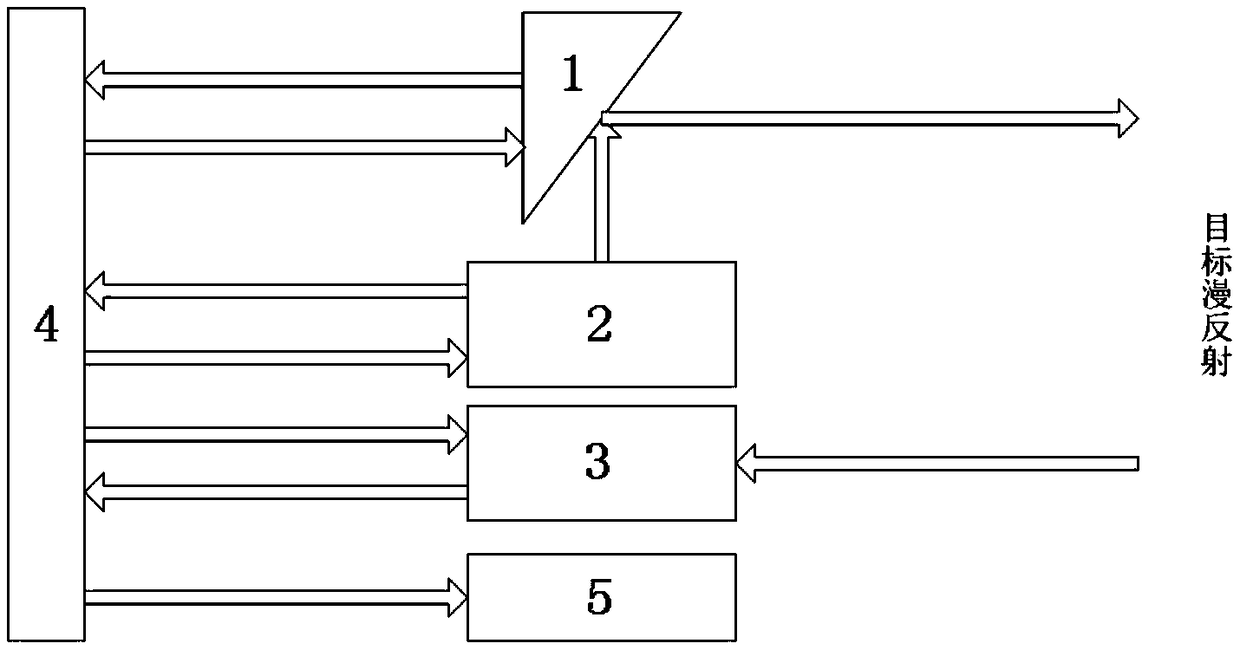
[0033] refer to figure 1 , is a structural schematic diagram of an embodiment of a micro-laser three-dimensional imaging radar based on a MEMS vibrating mirror provided by the present invention. The micro-laser three-dimensional imaging radar includes a two-dimensional MEMS vibrating mirror 1, a laser 2, a laser detector 3, and a drive control system 4 and an imaging display system 5;

[0034]...


PUM


Abstract

The invention discloses an MEMS galvanometer-based micro laser three-dimensional imaging radar and an imaging method. The MEMS galvanometer-based micro laser three-dimensional imaging radar comprisesa two-dimensional MEMS galvanometer, a laser, a laser detector, a driving and control system and an imaging display system; a laser pulse emitted by the laser is reflected by the two-dimensional MEMSgalvanometer, and the reflected laser pulse is refracted to a certain scanning point in a target area; the angle of the MEMS galvanometer is extracted in real time, and the coordinates of the scanningpoint in the target area which is irradiated by the refracted light of the MEMS galvanometer at the angle are obtained; the coordinates of corresponding scanning points in the target area of a plurality of laser pulses are obtained, so that the target area can be divided into a series of dot matrixes; the laser detector receives light which is formed after the laser pulses are diffusely reflectedby the target, so that the laser detector can measure target distance information; the driving and control system is used for driving and controlling the two-dimensional MEMS galvanometer, the laserand the laser detector to work synchronously and sending the feedback information of the two-dimensional MEMS galvanometer, the laser and the laser detector to the imaging display system; and the imaging display system generates the three-dimensional image of the target area according to the dot matrixes and the target distance information. The MEMS galvanometer-based micro laser three-dimensionalimaging radar and the imaging method have the advantages of large scanning field angle, high scanning frequency and simple structure.

Description

technical field [0001] The invention belongs to the technical field of photoelectric instruments, and in particular relates to a micro-laser three-dimensional imaging radar and an imaging method based on a MEMS (Micro-Electro-Mechanical System, MEMS) vibrating mirror. Background technique [0002] The concept of Lidar (LIDAR: Light Detecion and Ranging) originated from microwave radar and is based on laser ranging technology; it usually uses a unit detector to measure and obtain distance information of each point in the field of view by using a two-dimensional point-by-point scanning method , through the synthesis process, the 3D image of the target is obtained by inversion. Due to its outstanding three-dimensional configuration capabilities, lidar technology is widely used in many fields such as surveying and mapping, industrial production, military reconnaissance, aerospace, navigation and guidance. [0003] The laser radar that uses single-point ranging to scan the targe...

Claims


Application Information

Patent Timeline
IPC IPC(8): G01S17/89G01S7/481
CPCG01S7/4817G01S17/89
Inventor 李宁雷雯雯张书文刘俊池陈希余常恒雷鸣
Owner HUBEI SANJIANG AEROSPACE WANFENG TECH DEV
Learn More