Device for fixating and adjusting the positions of vertebrae in vertebral surgical operations

Inactive Publication Date: 2000-02-22
OLERUD SVEN
View PDF4 Cites 80 Cited by
  • Summary
  • Abstract
  • Description
  • Claims
  • Application Information

AI Technical Summary

Benefits of technology

The object of the present invention is to eliminate the aforesaid drawbacks of known devices for locking and fixating generally rod-shaped implants, and to provide a d

Problems solved by technology

The devices used to this end are often bulky and can cause the patient considerable discomfort.
These known devices are ofte

Method used


Image

  • Device for fixating and adjusting the positions of vertebrae in vertebral surgical operations
  • Device for fixating and adjusting the positions of vertebrae in vertebral surgical operations
  • Device for fixating and adjusting the positions of vertebrae in vertebral surgical operations

Examples


Embodiment Construction

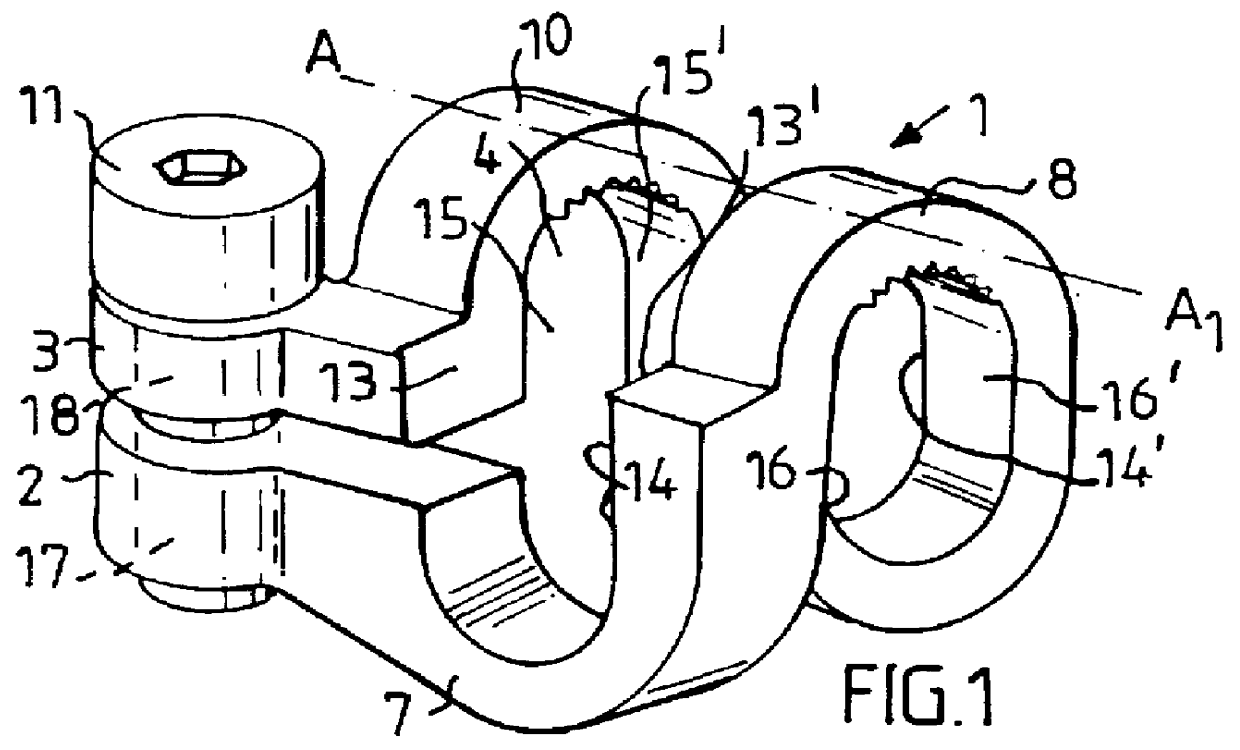
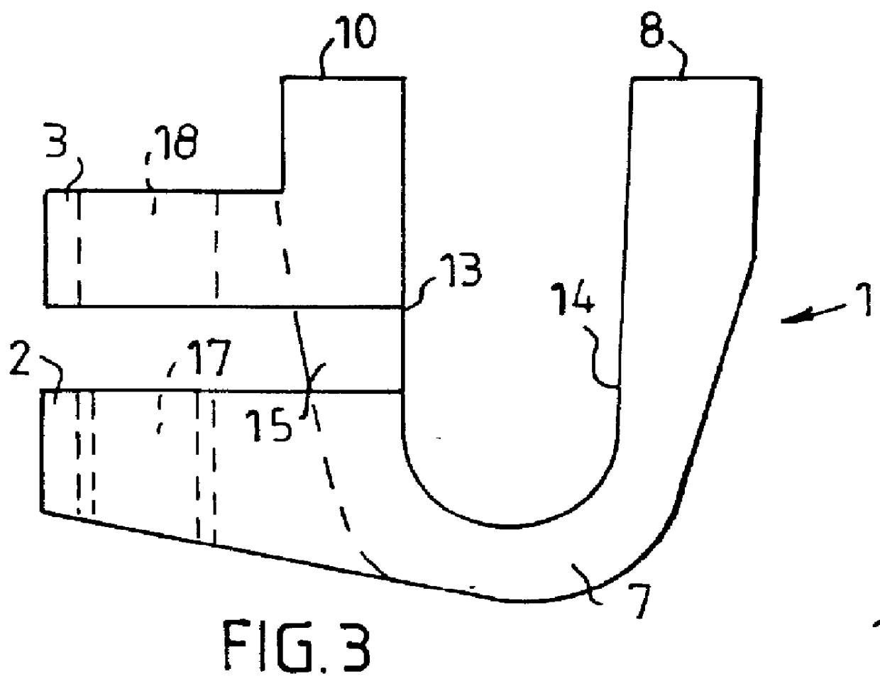
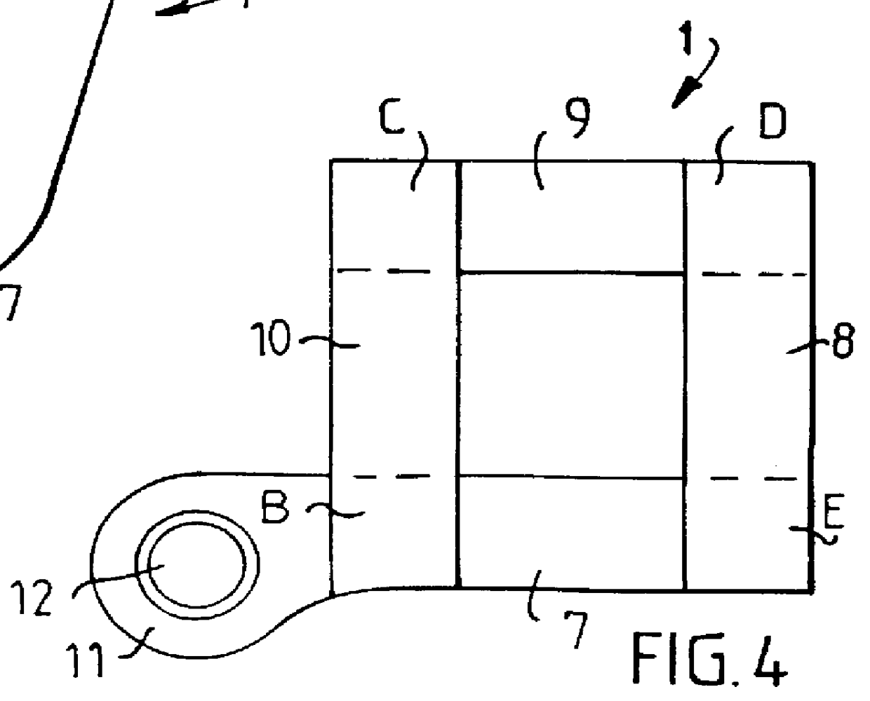
FIGS. 1 through 4 illustrates the main components of one embodiment of an inventive device. As will be seen from these Figures, the device comprises an elongated locking member 1 having two free ends 2, 3 and including a so-called hooped holding and clasping part 4 which embraces the rod-shaped implant elements 5, 6 and which from an initially flat state is curved about a centre line A--A through an angle of 180.degree., so as to form two bottom part-hoops 7, 9 and two top part-hoops 8, 10 which pair-wise embrace the rod-shaped implant elements 5, 6, wherein the free ends 2, 3-of the locking member include the hooped holding and clasping part 4 and are provided with locking and displacement means 11 which enable respective free ends to be displaced relative to one another and locked in their set positions. Each of the free ends 2, 3 includes a flange which extends out from the hooped holding and clasping part 4 essentially at right angles thereto, said flanges each having a screw-th...


PUM


Abstract

PCT No. PCT/SE96/00340 Sec. 371 Date Jan. 12, 1998 Sec. 102(e) Date Jan. 12, 1998 PCT Filed Mar. 18, 1996 PCT Pub. No. WO96/32070 PCT Pub. Date Oct. 17, 1996The present invention relates to a device for fixating and adjusting the position of vertebrae in conjunction with vertebral surgical operations, comprising two mutually crossing and generally rod-shaped implant elements. For the purpose of locking the implant elements together, the device (1) further comprises four generally parallel, elongated elements (B, C, D, E) projected onto a plane that passes through two of the elements whose ends are generally located in the corners of a parallelogram, preferably a square. The ends of the elements are mutually joined together in pairs by mutually parallel part-hoops (7, 9; 8, 10) which curve outwards from the ends of the elongated elements, wherein the pair of part-hoops (7, 9) at one end of an elongated element are perpendicular to the pair of part-hoops (8, 10) at the other end thereof, wherein the part-hoops of each said pair embrace a rod-shaped implant element (5, 6, 11a, 17) together with a respective adjacent, crossing rod-shaped element, wherein those sides (13, 14, 13', 14'; 15, 16, 15', 16') of the elongated elements that lie against a rod-shaped element are essentially flat and essentially parallel with respective opposing sides of an adjacent elongated element in fixating and positionally adjusting a vertebra.

Description

The present invention relates to a device intended for fixating and adjusting the positions of vertebrae in vertebral or spinal surgical operations and including two mutually crossing and generally rod-shaped implant elements.DESCRIPTION OF THE BACKGROUND ARTMany different solutions concerned with locking and fixating two generally rod-shaped implant elements placed one on the other such as to correct and stabilize adjacent vertebra have been proposed in the art. The devices used to this end are often bulky and can cause the patient considerable discomfort. These known devices are often difficult to apply and have a complicated and relatively often illogical design, making handling of the devices difficult.BRIEF DESCRIPTION OF THE INVENTIVE CONCEPTThe object of the present invention is to eliminate the aforesaid drawbacks of known devices for locking and fixating generally rod-shaped implants, and to provide a device which can be readily manipulated quickly and smoothly and which wi...

Claims


Application Information

Patent Timeline
IPC IPC(8): A61B17/70A61B17/58
CPCA61B17/7041A61B17/7049A61B17/7032A61B17/7052
Inventor OLERUD, SVEN
Owner OLERUD SVEN
Why Eureka
Try Eureka