Hydrokinetic torque converter

Inactive Publication Date: 2000-04-18
LUK GETRIEBE SYST
View PDF10 Cites 16 Cited by
  • Summary
  • Abstract
  • Description
  • Claims
  • Application Information

AI Technical Summary

Benefits of technology

An object of the invention is to provide a hydrokinetric torque converter which renders it possible to employ a relatively simple, compact a

Problems solved by technology

A drawback of such transmissions is that they are complex and expensive because each such transmission comprises a large number of in pa

Method used


Image

  • Hydrokinetic torque converter
  • Hydrokinetic torque converter
  • Hydrokinetic torque converter

Examples


Embodiment Construction

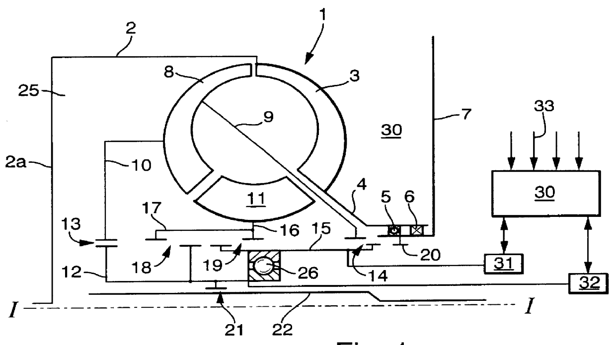
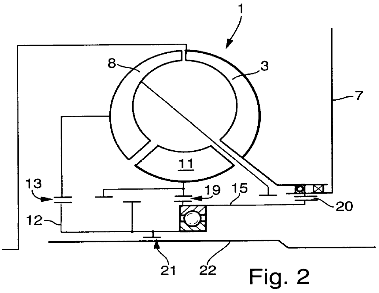
Referring first to FIG. 1, there is shown one-half of a hydrokinetic or hydrodynamic (hereinafter called hydrokinetic) torque converter 1 which embodies one form of the present invention. The housing 2 of the torque converter 1 is rotatable about an axis I--I and contains a pump 3, a turbine 8 and a stator 11. A substantially radial wall 2a of the housing 2 is adjacent and is connected to the rotary output member of a suitable prime mover, e.g., to the crankshaft or the camshaft of an internal combustion engine in the power train of a motor vehicle.

The pump 3 is rotated by and its vanes or blades (not specifically shown in FIG. 1) can be affixed to or of one piece with the housing 2. A connector 4 is provided to operatively connect the pump 3 with a bearing 5 and a sealing element 6 which are provided to rotatably and sealingly couple the pump 3 with the case 7 of a transmission.

The turbine 8 is installed in the housing 2 between the pump 3 and the aforementioned substantially radia...


PUM


Abstract

A hydrokinetic torque converter for use with a transmission in the power train of a motor vehicle has a housing rotatable by the engine and containing a pump, a turbine and at least one stator as well as a rotary output device connected to the input shaft of the transmission. The pump is normally rotatable by the housing; the turbine is rotatable (a) by the fluid which is circulated by the pump or (b) by the housing in response to engagement of a lockup clutch; and the stator can be connected to the stationary case of the transmission or is rotatable by the circulating fluid. First and second hubs are non-rotatably but axially movably mounted on the output member and are respectively connectable with the turbine and the stator by suitable clutches. The hubs can move axially relative to the output device between several positions in one of which the turbine can drive the input element of the transmission in a forward direction, in another of which the stator can rotate the input element in a direction to drive the vehicle rearwardly, and in a third of which the transmission is in neutral gear.

Description

The invention relates to improvements in hydrokinetic or hydrodynamic torque converters.A standard hydrokinetic torque converter comprises certain basic components including a housing, a pump which is confined in the housing and receives torque from a suitable prime mover (such as by way of the housing), a turbine in the housing, and an optional stator in the housing. The turbine receives torque from the pump and drives an output element, e.g., the input shaft of a transmission if the torque converter is installed in the power train of a motor vehicle between an internal combustion engine (which drives the housing) and a variable speed transmission, particularly an automated transmission. The ratio of the transmission is or can be changed by one or more suitable actuators to shift the transmission into neutral, reverse or a selected forward gear. When utilized in conjunction with an automated transmission, a torque converter can serve as a means for starting, as a means for equalizi...

Claims


Application Information

Patent Timeline
IPC IPC(8): F16H61/38F16H61/60F16H45/00
CPCF16H61/60F16H2045/0294F16H2045/005F16H2045/002
Inventor GRADU, MIRCEAWAGNER, UWEMIDDELMANN, VOLKERKOZAREKAR, SHAILESHMAUCHER, EDMUNDREIK, WOLFGANG
Owner LUK GETRIEBE SYST
Why Eureka
Try Eureka