Lamp reflector with adjustable curvature

a technology of reflectors and curvatures, applied in the direction of lighting and heating equipment protection devices, lighting heating/cooling arrangements, lighting and heating equipment, etc., can solve the problem of limiting the efficient use of these devices to a relatively small range of applications

Inactive Publication Date: 2000-04-25
CRONK PAUL ANDREW
View PDF9 Cites 113 Cited by
  • Summary
  • Abstract
  • Description
  • Claims
  • Application Information

AI Technical Summary

Problems solved by technology

These known devices have the disadvantage that their rigid, non-adjustable, designs limit their efficient use to a relatively small range of applications.

Method used


Image

  • Lamp reflector with adjustable curvature
  • Lamp reflector with adjustable curvature
  • Lamp reflector with adjustable curvature

Examples


Embodiment Construction

)

Throughout the drawings, like numerals will be utilized to represent similar features, except where expressly otherwise indicated.

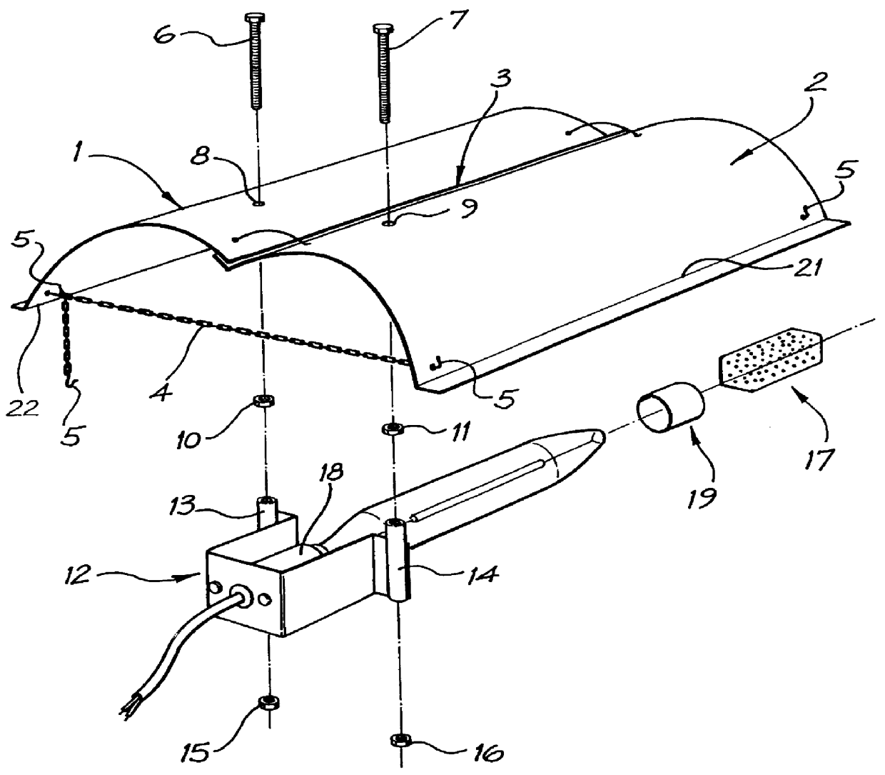
Also, throughout the specification, the term "a double parabolic" is utilised to describe the shape of the device when it is in its flexed position, and retained against the bias of it's normal resilience, as for example, shown in FIG. 1 of the drawings. In considering this definition, it should be appreciated that any size, shape or width of double parabolic or similar shape should be considered to fall within the scope of this definition.

The present invention provides an adjustable light reflector device comprising a resilient reflective skin, flexed to form a double parabolic shape, which is held in place against its resiliency by adjustable retainers located at each end of the skin and an independently adjustable lamp mount which attaches to the skin when it is in the retained position. A slide on V-shaped perforated heat shield is preferably attache...


PUM


Abstract

PCT No. PCT/AU95/00303 Sec. 371 Date Mar. 10, 1998 Sec. 102(e) Date Mar. 10, 1998 PCT Filed May 24, 1995 PCT Pub. No. WO96/37732 PCT Pub. Date Nov. 28, 1996An adjustable reflector device is disclosed. The device consists of an adjustable double parabolic reflective skin (1,2) with an adjustable lamp mount (12), incorporating a V-shaped perforated heat shield (17), attached. The two part reflective skin (1,2) forms a double parabolic shape when flexed back against a reinforced spine (3). This flexible shape is secured by lengthwise adjustable chain retainers (4) attached at both ends of the skin (1,2). The lamp mount (12) slides onto a pair of threaded bolts (6,7) secured to the skin and adjustment is achieved by tightening or loosening the appropriate nuts (15,16). The heat shield (17) slides onto the lamp fitting (18) and is positioned appropriately to deflect incident heat and light. This device can be used to provide variable conditions of artificial illumination.

Description

This invention relates to improvements in devices for reflecting light emitted by artificial sources.DESCRIPTION OF THE PRIOR ARTModerm industries requirements for artificial lighting are extensive, varied, and constantly expanding.Many types of reflector devices associated with artificial illumination of industrial spaces are currently known, but these all require that a fixed shape and / or a fixed lamp mounting position within that shape be precisely specified to create optimal light distribution for a particular purpose. For example, a `chinaman hat` reflector might commonly be used in a situation where a wide, uniform spread of light is required. In this case, the spreading of light is largely dependant on the fixed internal angle of the cone shaped `chinaman hat` reflector. The uniformity of light emitted is therefore largely dependant on the non-adjustable lamp positioning within that reflector. These known devices have the disadvantage that their rigid, non-adjustable, designs...

Claims


Application Information

Patent Timeline
Patent Type & Authority Patents(United States)
IPC IPC(8): F21V7/00F21V7/16F21V19/02F21V15/06F21V11/00F21V11/14F21V17/00F21V17/06F21V15/00F21V7/06F21V7/10F21V14/04F21V17/04F21V29/00F21V29/15
CPCF21V7/10F21V7/16F21V11/14F21V17/04F21V29/15F21V19/02F21V7/005F21V17/06F21Y2103/00
Inventor CRONK, PAUL ANDREW
Owner CRONK PAUL ANDREW
Why Eureka
Try Eureka