
Led light

Inactive Publication Date: 2007-02-08
CENT TOOLS
View PDF10 Cites 45 Cited by
  • Summary
  • Abstract
  • Description
  • Claims
  • Application Information

AI Technical Summary

Benefits of technology

[0013] It an object of the present invention to provide a portable light that is free of filament shading or bright spots.

Problems solved by technology

Portable lighting devices of the type frequently known as shop, work, utility or task lights, and other portable lighting devices have limitations in that they often fail to provide a clean light beam.
These obstructions to the light beam may be caused by the interference of a filament with the emitted light beam.
General lighting such as fluorescent overhead lighting typically available in a workspace, such as in a garage, is insufficient for close work.
The shadows cast by the many components of an object of work make working without directed illumination nearly impossible.
One limitation of the shop light is finding a suitable location for hanging.
The light output direction shifts, thereby reducing its usefulness.
Shop lights are adequate for general work, but do not provide adequate light for working in close or confined work areas.
Moreover, these types of lights are usually too large and cumbersome to fit into constricted workspaces.
As a result, light cannot be directed into the desired locations due either to obstructions or the physical size of the components.
Also, many of the existing work or utility lights reach uncomfortably high temperatures over an extended use period and these can become hazardous to the user when used in a close work space.
Thus, shop lights often emit an “overspray” of light.
This “overspray” is very distracting and can cause eye irritation.
The eye irritation can also lead to time consuming and dangerous working conditions.
Even with the bright white light LEDs currently available, the LED light source fails to provide a light source having optic tolerances that provide a sufficiently clean, broad and intense light.

Method used


Image

  • Led light
  • Led light
  • Led light

Examples


Embodiment Construction

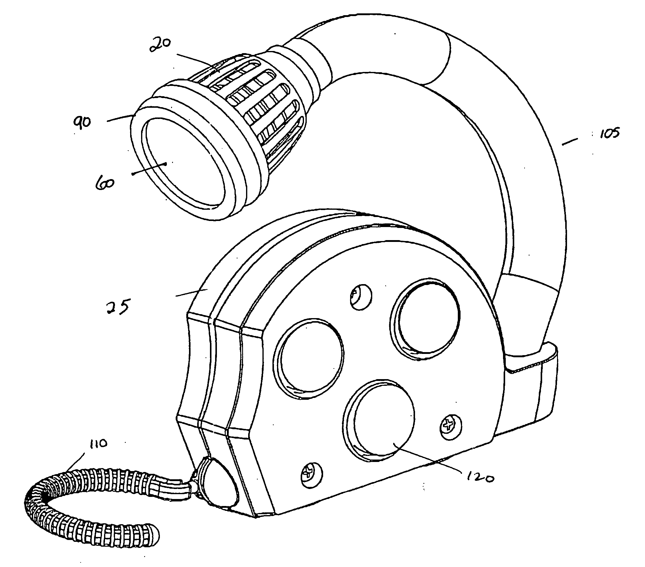
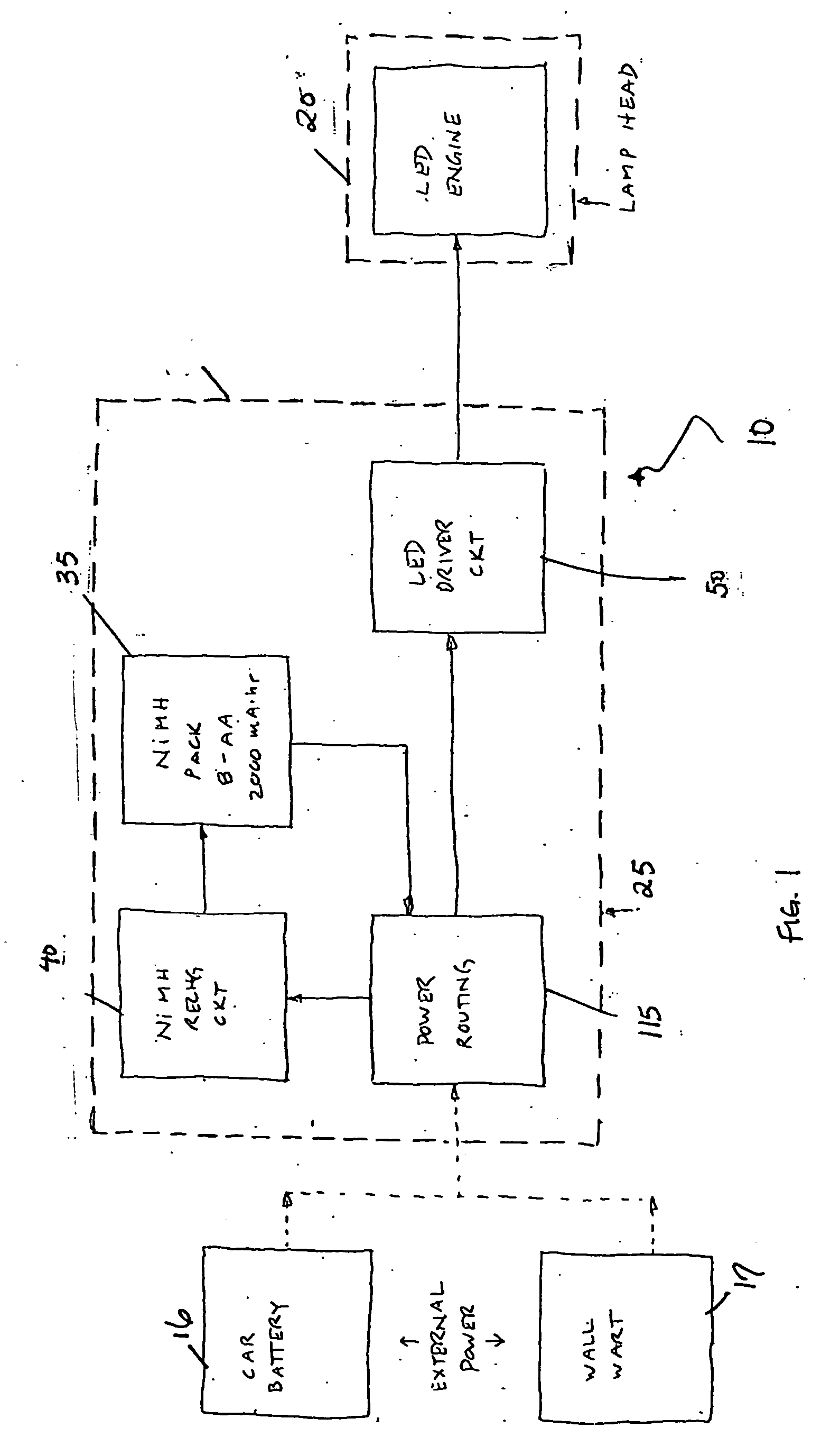
[0032] Referring to the drawings and, in particular, FIG. 1 there is illustrated an LED light according to the present invention generally represented by reference numeral 10. LED light 10 preferably has a lamp head 20 and a housing 25. Housing 25 contains a power routing element 115, a rechargeable battery 35, recharge circuitry 40, and LED (light emitting diode) driver circuitry 50.

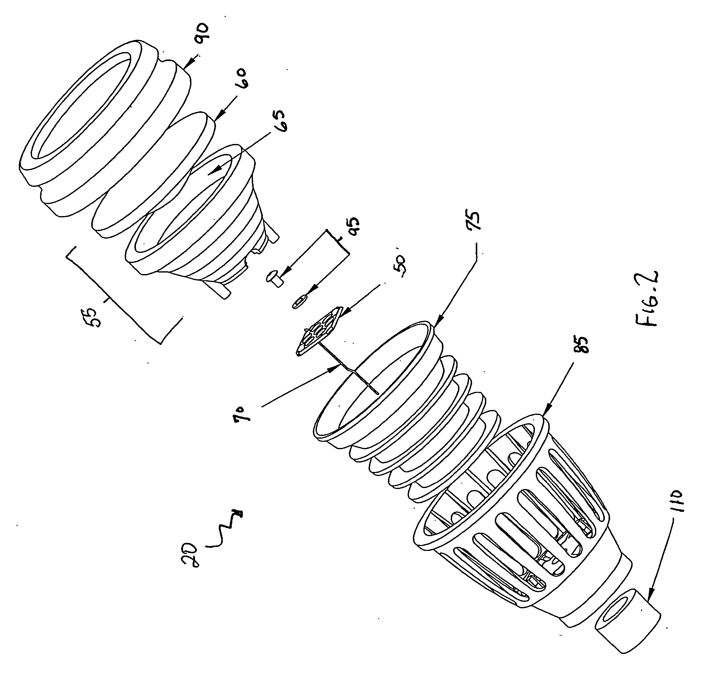
[0033] As shown in FIGS. 2 and 3, lamp head 20 houses an LED module 50, an optic assembly 55 comprising a lens 60 and a reflector 65, a power lead 70, and a heat sink 75. LED module 50 is preferably a packaged array of a multiplicity of individual LED semiconductor chips disposed on a substrate. The substrate is preferably engineered for optimizing thermal performance and heat transfer, such as substrates supplied by Lamina Ceramics of Westampton, N.J. LED module 50 preferably incorporates means for electrostatic discharge protection.

[0034] LED light 10 employs an LED optical system of the type disclo...


PUM


Abstract

The lamp head of an LED utility light provides LED elements, a housing, a power source, and optical means produces from the LED element output a substantially clean and uniform light beam over at least 24-32 inches from the lamp head. In another embodiment, a flexible stalk is connected at one end to the housing and at the other to the lamp head. Yet another embodiment shows a LED module, secondary optics and a heat sink; a renewable power source, a flexible neck linked at one end to the housing and at the other supporting a lamp head housing an LED elements array. Optical means produces a substantially uniform light beam from the LED element to a distance of at least 5 feet from the lamp head, the flexible neck having quick-release capacity to allow alternation between white LED die and blue ultraviolet LED die.

Description

BACKGROUND OF THE INVENTION [0001] 1. Field of the Invention [0002] The present invention relates to a light-emitting diode (LED) light assembly. More particularly, the present invention relates to a readily positionable LED light assembly that is adapted to provide a substantially clean and uniform beam of light. [0003] 2. Description of the Prior Art [0004] Portable lighting devices of the type frequently known as shop, work, utility or task lights, and other portable lighting devices have limitations in that they often fail to provide a clean light beam. Often, the emitted light has bright or shady spots. These obstructions to the light beam may be caused by the interference of a filament with the emitted light beam. A clean and uniform beam of light is necessary to provide a bright beam over a distance. [0005] Work lights also require a clean and bright beam of light. One of the essential requirements for work in a close or confined work space is adequate lighting. Non-limiting ...

Claims


Application Information

Patent Timeline
IPC IPC(8): F21L4/04
CPCF21L4/04F21V21/0832F21V21/088F21V29/83F21V21/32F21Y2101/02F21V29/20F21V21/096F21Y2115/10
Inventor OFFILER, STEPHEN B.GENDREAU, DAVIDPOISSON, MARCUS
Owner CENT TOOLS
Learn More