Lamp cover and electronic cigarette using the same

a technology of electronic cigarettes and covers, applied in the direction of lighting devices, lighting support devices, lighting and heating apparatuses, etc., can solve problems such as fatigue of the eyelids

Inactive Publication Date: 2014-10-02
KIMREE HI TECH
View PDF12 Cites 41 Cited by
  • Summary
  • Abstract
  • Description
  • Claims
  • Application Information

AI Technical Summary

Benefits of technology

[0028]When implementing the embodiments of this invention, the following advantageous effect can be achieved: the lamp cover with different colors is added onto the previous lamp cover by changing the material and configuration of the lamp cap of electronic cigarette. In this way, the light emitted from the built-in light emitting diode passes through the lamp cover with different colors and then changes its color, so that the electronic cigarette can result in bright and colorful light or color effect and further meet user's individual requirement. Meanwhile, air inlets can be arranged on the contact surface of the first and second lamp caps that form the lamp cover, thus achieving more hidden arrangement for the air inlet.

Problems solved by technology

Although such electronic cigarette has good simulation effects, single light color still results in aesthetic fatigue over a long time of usage.

Method used


Image

  • Lamp cover and electronic cigarette using the same
  • Lamp cover and electronic cigarette using the same
  • Lamp cover and electronic cigarette using the same

Examples


first embodiment

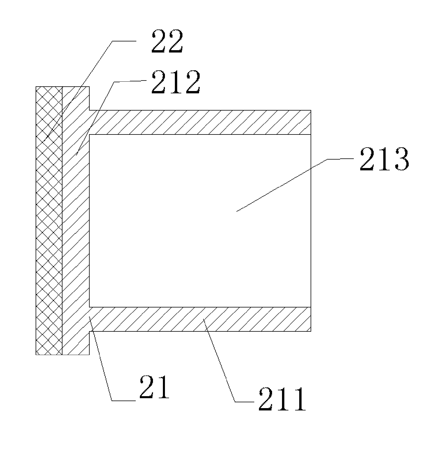
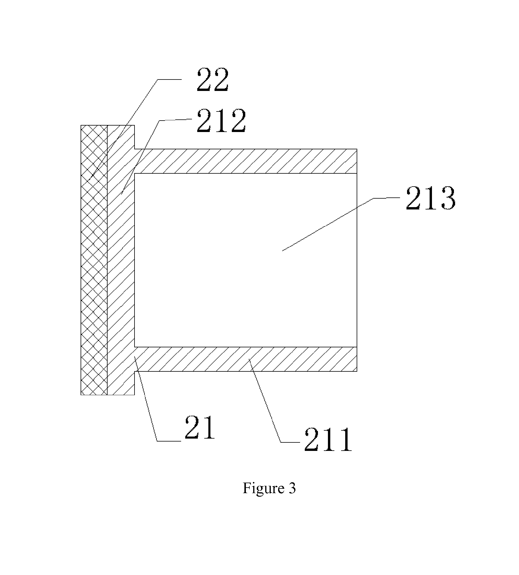
[0038]As shown in FIG. 3, in a first preferred embodiment of this invention, a lamp cover 2 comprises a first lamp cap 21 and a second lamp cap 22. The first lamp cap 21 is comprised of a top cover 212 and lamp cap columns 211, wherein the latter have a receiving cavity 213 and extend axially from a bottom surface of the top cover 212. The second lamp cap 22 is located on and further covers an upper end surface of the top cover 212, and its surface shape is adaptive with that of the upper end surface of the top cover 212. The upper end surface of the top cover 212 can be in the shape of square, circle or ellipse, which is covered by the second lamp cap 22. The two mentioned herein can be connected together detachably or fixedly. In the case of detachable connection, the following structural design can be adopted: at least one protrusion (not shown in figures) is disposed on the surface of the second lamp cap 22 that faces the upper end surface of the top cover 212, and at least one ...

second embodiment

[0041]As shown in FIG. 4, in a second preferred embodiment of this invention, a first lamp cap 21 is comprised of a top cover 212 and lamp cap columns 211, wherein the latter have a receiving cavity 213 and extend axially from a bottom surface of the top cover 212. The cross section of the second lamp cap 22 is U-shaped, and it can be designed to be a hollow cylinder. Besides, the external diameter of the second lamp cap 22 is adaptive with the receiving cavity 213 in such a way that the second lamp cap 22 is sleeved by and pressed against the receiving cavity 213. Herein, the first and second lamp caps 21 and 22 are made of semi-transparent material. For example, the first lamp cap 21 is semi-transparent yellow polyvinyl fluoride (PVC) and the second lamp cap 22 is semi-transparent ivory white acrylonitrile-butadiene-styrene (ABS) plastic. Also the first and second lamp caps 21 and 22 can be made of electroplated or sprayed transparent material. For instance, the first lamp cap 21 ...

third embodiment

[0042]As shown in FIG. 5, in a third preferred embodiment of this invention, the first lamp cap 21 is made of transparent or semi-transparent material such as PVC, ABS, PS or PMMA in the first preferred embodiment. The first lamp cap 21 is comprised of a top cover 212 and lamp cap columns 211 extending axially from a bottom surface of the top cover 212. The second lamp cap 22 is a hollow cylinder made of metal material such as copper and aluminium alloy, while its external surface can also be subjected to electroplated or oxidation treatment. The second lamp cap 22 can also be made of transparent or semi-transparent material such as PVC, ABS, PS or PMMA in the first preferred embodiment. The external surface of the second lamp cap 22 is provided with threads, and its end surface being pressed against the lamp cap column 211 is provided with a concave part 224 for receiving the lamp cap column 211. Surface shape of the concave part 224 is adaptive with the lamp cap column 211 so that...


PUM


Abstract

This invention discloses a lamp cover and an electronic cigarette. The lamp cover comprises a first lamp cap and a second lamp cap which two are connected with each other detachably or fixedly to from the whole lamp cover. The light emitted from the light emitting diode will change in its color when passing through the lamp cover, so that the electronic cigarette using such lamp cover can result in bright and colorful light or color effect and further meet user's individual requirement. Meanwhile, air inlets can be arranged on the contact surface of the first and second lamp caps that form the lamp cover, thus achieving more hidden arrangement for air inlet and more aesthetic appearance without influencing the smoothness of airflow.

Description

CROSS-REFERENCE TO RELATED APPLICATIONS[0001]This application is a continuation of International Patent Application No. PCT / CN2013 / 073286, with an international filing date of Mar. 27, 2013, designating the United States, now pending. The contents of these specifications are incorporated herein by reference.FIELD OF THE INVENTION[0002]This invention relates to a technical field of daily electronic products, and more particularly to a lamp cover and an electronic cigarette using the same.BACKGROUND OF THE INVENTION[0003]Electronic cigarette is a simulated electronic tobacco product, by which smoking effect is achieved when people suck some atomizing tobacco tar. Since a cigarette butt is accompanied with twinkling firelight during smoking in the case of a litten cigarette, a light emitting diode (LED) is disposed at the end opposite to a suction nozzle in the electronic cigarette for the purpose of fitting people's usage habit and achieving simulation effect, which LED will twinkle d...

Claims


Application Information

Patent Timeline
Patent Type & Authority Applications(United States)
IPC IPC(8): A24F47/00F21V21/00A24F40/485
CPCF21V21/00A24F47/002A24F40/485
Inventor LIU, QIUMING
Owner KIMREE HI TECH
Why Eureka
Try Eureka