Traveling mechanism in a lifting arrangement which is moveable on rails

a technology of travel mechanism and lifting arrangement, which is applied in the direction of runways, ways, hoisting equipment, etc., can solve the problems of severe wear or even destruction of the travel mechanism, and the pendulum suspension is unsuitable for laterally cantilevering the boom of two-rail cranes

Inactive Publication Date: 2000-05-09
TEREX MHPS
View PDF6 Cites 52 Cited by
  • Summary
  • Abstract
  • Description
  • Claims
  • Application Information

AI Technical Summary

Problems solved by technology

A disadvantage in these known traveling mechanisms and rails consists in that, although they are very well suited for use with pendulum type suspensions, these traveling mechanisms are severely worn or even destroyed when used with a rigidly suspended rail which is required for absorb

Method used


Image

  • Traveling mechanism in a lifting arrangement which is moveable on rails
  • Traveling mechanism in a lifting arrangement which is moveable on rails
  • Traveling mechanism in a lifting arrangement which is moveable on rails

Examples


Embodiment Construction

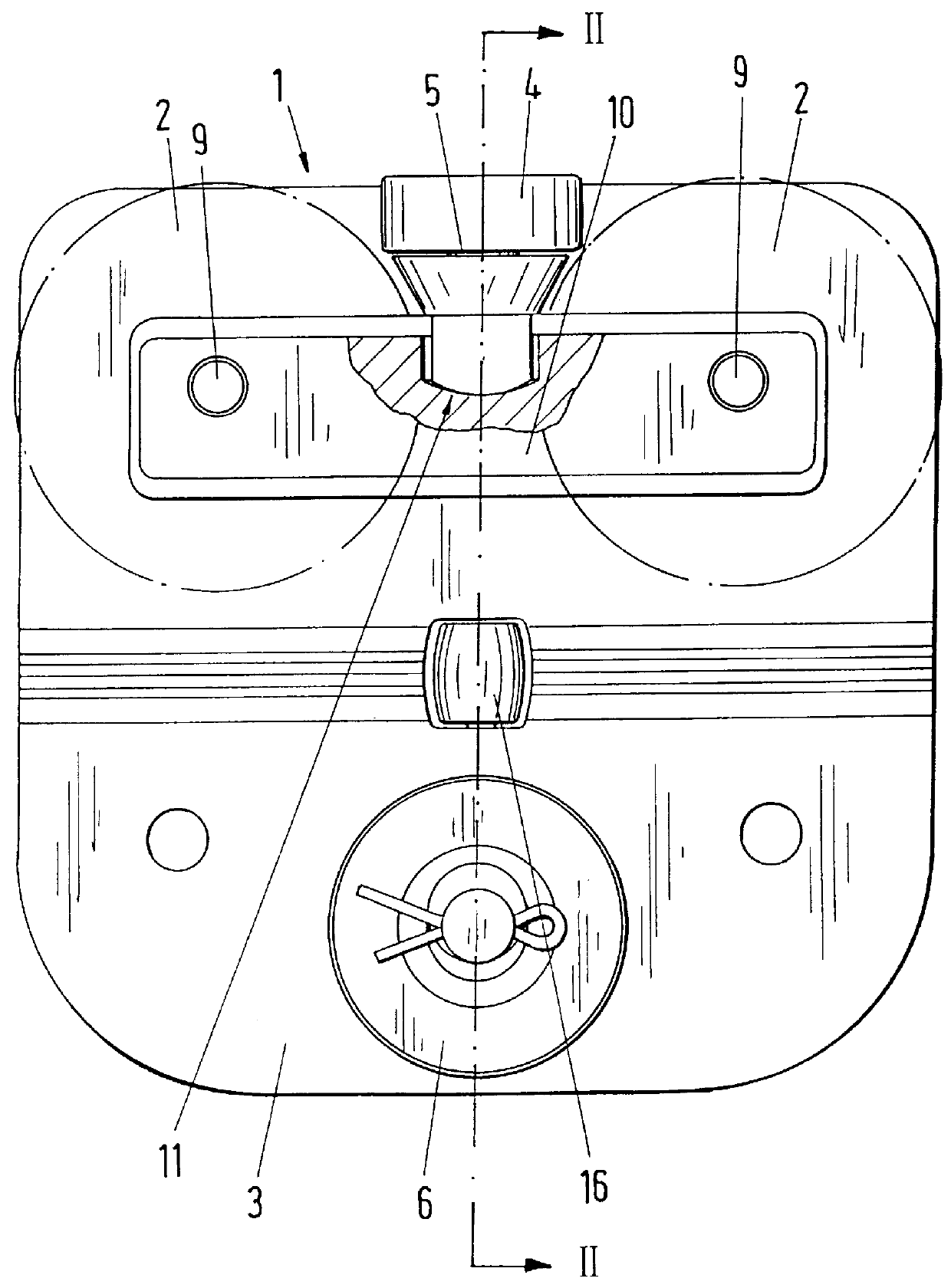
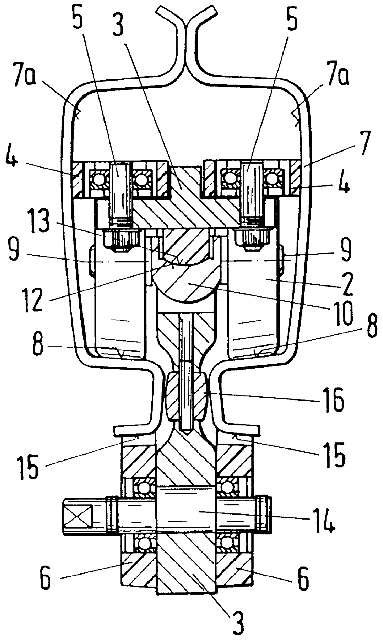
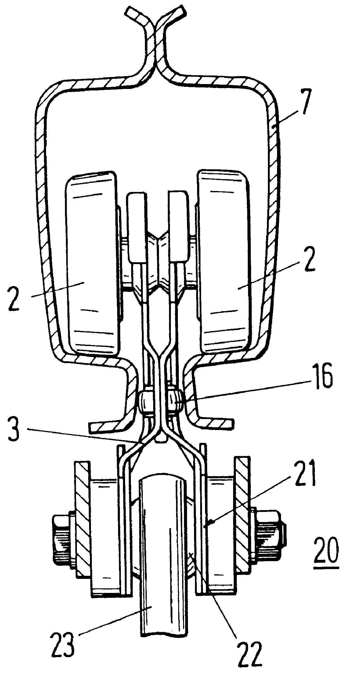
Referring to FIG. 1 a traveling mechanism 1 for a lifting device which is movable on a rail includes a connection element 3 on which two pairs of cambered running wheels 2 are arranged one behind the other along the traveling direction of the traveling mechanism. Each pair includes two of the running wheels 2 parallel to one another on opposing sides of the connection element 3. Of course, it is also possible to arrange the running wheels 2 so that they are offset relative to one another on both sides of the connection element 3. Support rollers 4 are rotatably mounted on the upper region of connection element 3 between the running wheels 2 along the traveling direction on both sides of the connection element 3. Vertical rotational axes 5 of the support rollers 4 are supported at the connection element 3. In the preferred embodiment, exactly one support roller 4 is mounted on each side of the connection element 3. Of course, the support rollers 4 can also be mounted in front of and / ...


PUM


Abstract

A traveling mechanism for a lifting device, especially for a lifting device having a laterally cantilevering boom, is movable on rails with at least two running wheels. A connection element for attaching a load to said traveling mechanism is supported in the rail by the running wheels which are arranged on both sides of the connection element. The connection element has, at the region projecting down out of the rail, at least one running roller which is freely rotatable about a horizontal axis and rolls on a horizontal outer running surface of the rail. To effectively divert horizontal forces and uniformly distribute the vertical forces to the running wheels, running wheel axles are rigidly connected with a running wheel carrier, and the running wheel carrier and connection element are swivelably connected by a universal type joint. In addition, at least one support roller is rotatably mounted at the connection element in the interior of the rail. The support roller freely rotates about a vertical axis and rolls along at least one of the side surfaces to transmit horizontal forces to the rail.

Description

1. Field of the InventionThe present invention relates to a traveling mechanism for a lifting device which is movable on rails, particularly for a lifting device having a laterally cantilevering boom.2. Description of the Related ArtA traveling mechanism of a lifting device which is movable on rails is known from the brochure "Kranbaukasten KBK [KBK Crane Building Blocks]" by Mannesmann Demag Fordertechnik AG. This prior art traveling mechanism has running wheels which run parallel to one another in pairs one behind the other in the traveling direction. The running wheels roll within an interior of a downward-opening hollow-section rail of an overhead track on substantially horizontal inner running surfaces of the rail. The running surfaces extend in the longitudinal direction of the rail and are sloped relative to one another. To attach a load, a connection element is connected with axles of the running wheels. The connection element projects downward out of the rail for attachment...

Claims


Application Information

Patent Timeline
IPC IPC(8): B66C11/00B66C11/06B66C11/10B66C9/08B61B13/06
CPCB66C7/04B66C11/10B66C11/06B66C9/08B66D2700/023
Inventor OSTHOLT, RUDIGERBECKER, KLAUSGABRIEL, KLAUS-DIETER
Owner TEREX MHPS
Why Eureka
Try Eureka