Method and arrangement for servoing and formatting magnetic recording tape

a magnetic recording tape and formatting technology, applied in the direction of recording on magnetic tapes, instruments, maintaining head carrier alignment, etc., can solve the problems of large helical scanning mechanism, limited application of helical scanning to data storage systems, wear on head parts and tapes, etc., to achieve the effect of reducing the number of helical scanning devices, complex and expensiv

Inactive Publication Date: 2000-05-09
CERTANCE
View PDF29 Cites 28 Cited by
  • Summary
  • Abstract
  • Description
  • Claims
  • Application Information

AI Technical Summary

Problems solved by technology

The application of helical scanning to data storage systems has been limited.
Repeated motion of the tape across the drum for large numbers of read and / or write operations for common computer data storage and retrieval purposes causes wear on the head parts and the tapes.
Also, the helical scanning mechanism tends to be large; complex and expensive.
For example, if there is some vibration of a scanner during the writing operation, it may be difficult to align the head with the data tracks during a read operation, particularly if the read operation is performed by a different scanner.
If a drive reading the tape cannot detect and compensate for such variations, that drive may not recover all of the data from all of the tracks.
Misalignment often prevents accurate recovery of stored data.

Method used


Image

  • Method and arrangement for servoing and formatting magnetic recording tape
  • Method and arrangement for servoing and formatting magnetic recording tape
  • Method and arrangement for servoing and formatting magnetic recording tape

Examples


Embodiment Construction

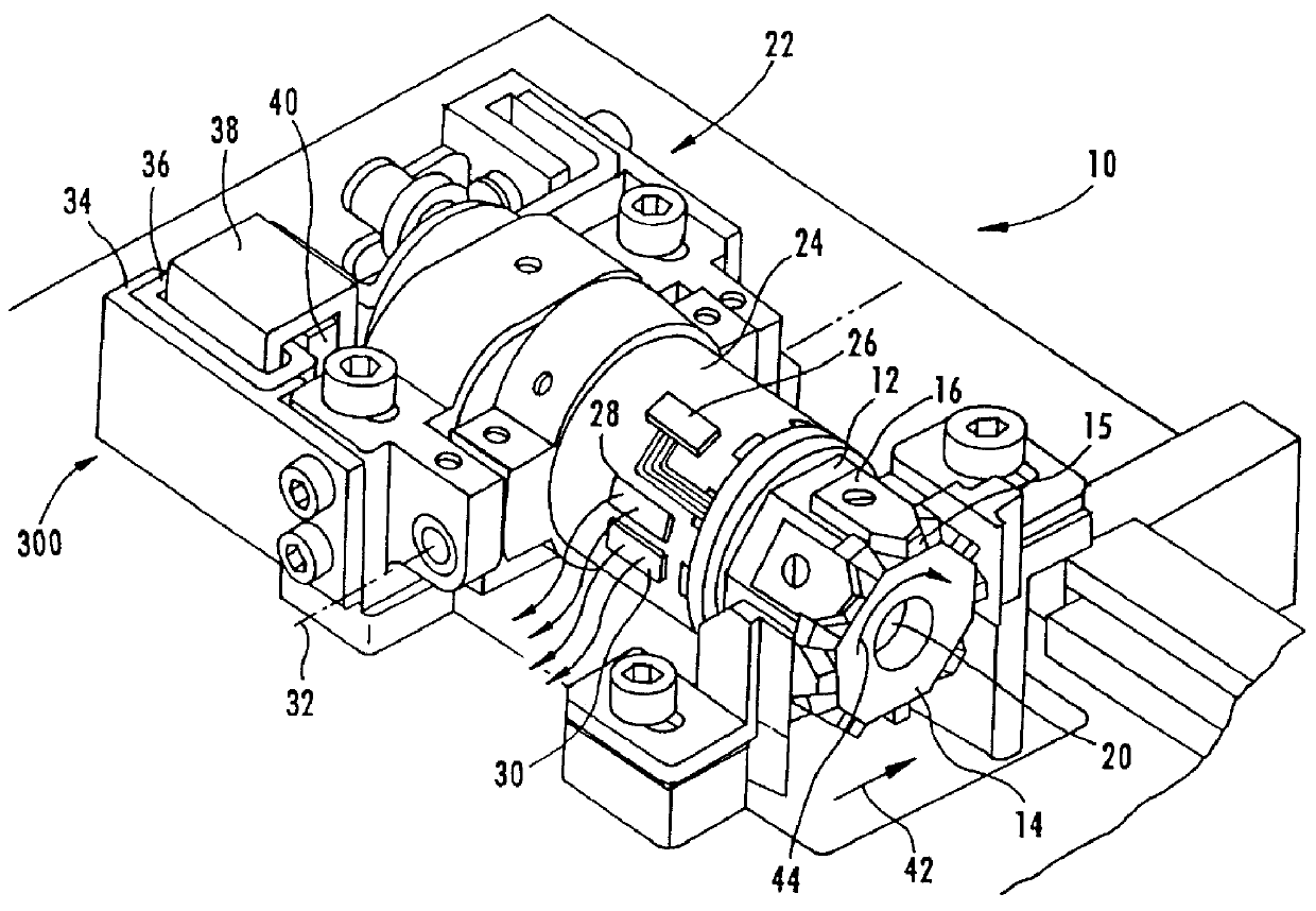
FIG. 1 depicts a perspective view of an arcuate scanner head assembly (ASHA) 10 which writes and reads a sequence of arcuate tracks on a recording tape. The scanner 10 has a drum 12 with an end face 14 at which a plurality of read and write transducers are mounted on support blocks 16. A magnetic transducer 15 is mounted at the forward tip of each support block 16. The drum 12 is rotated by a rotatable shaft 20 which is mounted for rotation in a motor / bearing assembly, generally indicated by reference numeral 22. Electrical signals are transferred to and from the transducers on the drum 12 by a conventional rotary transformer assembly having a rotary piece and a stator piece (not visible in the illustrated view). The drum 12 (with the rotor) is fixed to rotate with the shaft 20. The housing 24 and stator are stationary with respect to the shaft 20. As the shaft 20 rotates together with the rotor and drum 12, electrical signals are written to and read from arcuate tracks on the recor...


PUM

PropertyMeasurementUnit
distanceaaaaaaaaaa
chord lengthaaaaaaaaaa
angleaaaaaaaaaa

Abstract

In an arcuate scanner, a read head senses passage over a reference stripe recorded on a moving recording tape. Detection and logic circuitry respond to the read head signal to detect the reference stripe and determine an angular position of the read head with respect to an index associated with the arcuate scanner head assembly. Timing operations of the arcuate scanner and alignment of the arcuate scanner head assembly with regard to an information recording region on the tape are controlled in reference to the detection of the reference stripe.

Description

The present invention relates to tape drives having an arcuate scanner, and more particularly to servo control of the scanner heads based on a reference point in the tape format to accurately control the operation of writing data to the tape and the operation of reading data from the tape.DESCRIPTION OF RELATED ARTConventional magnetic tape drive systems provide a reel-to-reel transport of magnetic tape past a fixed recording / reading location where a stationary single-track or multiple-track head is positioned. Recording and playback are performed longitudinally with respect to the tape by moving the tape on its longitudinal axis past the stationary record / playback head mechanism. In the stationary head tape drive, a plurality of transversely-aligned heads are fixedly positioned with respect to the tape during recording and playback. The recording heads place a plurality of parallel longitudinally-extending tracks on the tape.Rotary head tape drive systems provide higher capacity. I...

Claims


Application Information

Patent Timeline
Patent Type & Authority Patents(United States)
IPC IPC(8): G11B15/12G11B21/04G11B5/008G11B5/588G11B5/53
CPCG11B5/0086G11B5/537G11B21/04G11B15/125G11B5/588
Inventor GOKER, TURGUYBUCHAN, WILLIAM
Owner CERTANCE
Why Eureka
Try Eureka